Week 18 Assignments
Table of Contents
Week 18 - Final Project Presentation
This week is special as we have to present our project in just 3 min. Here is a briefing with all relevant and required information.
Description
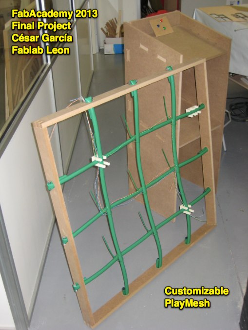
My final project is a customizable mesh, that can be used to play several games and activities. Technically speaking, it's press fitted frame that holds a mesh of processors, controlling photosensors to trigger events. Each node has also a RGB led, directly addressable. Data is sent using RS-485 IC to a central unit that changes each sensor's color according to currrent game rules. Games can be selected using physical buttons attached to central station inside a custom build stand, with double heigth for both adults and children.
This is project is currently unfinished, but several advances have been made in key areas. This is a photo of current prototype version:
Design considerations
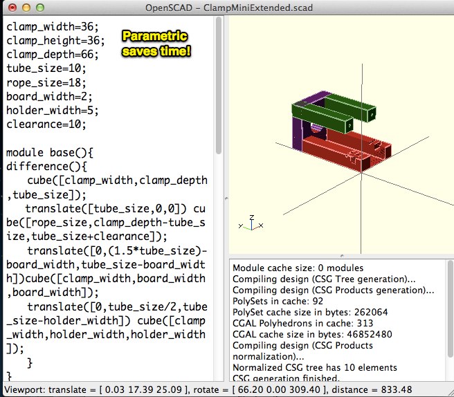
Since the first moment I decided to use OpenSCAD to do all my designs for FabAcademy. Even though sometimes it can be a bit cumbersome for a piece, it can pay off if it's designed parametrically and changes have to be done along the way. Given I didn't knew the material I was going to use for the mesh itself, I decided to do make it easily customizable.
I printed a couple of test pieces and I discovered they could be used for single lines, but not for the joints. I only had to change the clamp depth parameter and get a new couple of them with the right proportions. In the end, designing parametrically for this kind of projects makes absolutely sense.
On the electronics part of the project I had lots of options, but I was not sure about how to make something that could scale and work reliably. I will sumarize them in these tables with the selected option.
Processor
| *ATMega Series* | *ATTiny* |
| Lots of pins | Limited number of pins |
| Large memory | Reduced memory |
| Native SPI, I2C, UART | USI compatible mode |
| Arduino compatible | Arduino-core compatible |
| Has libraries for Modbus, DMX512, i2c | Has libraries for i2c |
Given the difference of price ($1.21 vs $1.35) in some models, the better connectivity options and the huge ammount of software available I opted for the ATMega. I decided to use the mesh to offer some basic lessons on programming for kids, and having the option of using either Arduino-compatible code or plain C is a big point for me.
Communication protocol
| *RS-485* | *i2c* |
| Industrial communication | Inter IC communication |
| Range: 1200m | Range:1-2m |
| High tolerance to noise | Over 2m can display noise problems |
| Physical layer only standard | Complete standard |
| DMX512 and Modbus are based on it | Compatible with itself |
| 32 devices per bus | 127 devices per bus |
| 2 cables | 2 cables plus common ground |
| Requires transceiver | Natively supported in ATMega |
| Long distances are no problem | Extending the bus requires repeaters and extra components |
This choice was a hard one, given I should purchase items outside the inventory in any case to meet the minimum size for the mesh (about 2.5m of cable lenght) and that I couldn't check in depth both options in advance. I decided to use RS-485 because of the better range, the extensibility and to be able to interact in the future with other DMX512 lightning controllers. Once protocol was chosen I ordered some samples from Maxim for MAX485 series controllers. They are quite expensive (3$ e.a) so I ordered also some TI DS17576 ($0.80 e.a.), that are a drop-in replacement that I would need to test extensively. This IC is supported on FreeModBus implementation (C code), so it would be quite easy to make it work.
For the mesh material, I decided to purchase a water hose and use it as the structure tubing: it's water resistant, cheap and can be used to transport all cabling inside without problems. For the cabling, I'm using RJ-45 pairs, recicled also.
Computer-controlled machining
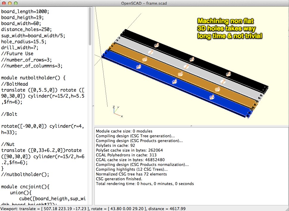
I decided to build a frame offer me a portable prototyping platform. It's a 1x1m MDF frame created using some leftovers from my "Make something big" assignment. I created it as a pressfit with some circles and nut and bolt holders to keep the mesh in it's place. These pieces were also designed in OpenSCAD.
When I was about to create the CAM jobs, I discovered it was not that easy to machine them in CNC because they were not flat. Instead of being able to define it as carving I had to create them as a 3D job, that takes ages compared to regular 2D ones. Also, as I had defined my piece translations based on a template, I could not isolate them to run them for the whole board. I have to define it for a single board, set them to 0,0 and then swap them everytime. Lesson learnt: If you have to mill something not flat, define them parametricaly independant from the other pieces, otherwise you won't be able to do it properly. I also learnt that MDF is a poor choice for this kind of projects as it breakes quite easily. I will try to create a final version using real wood or HDPE.
3D Printing
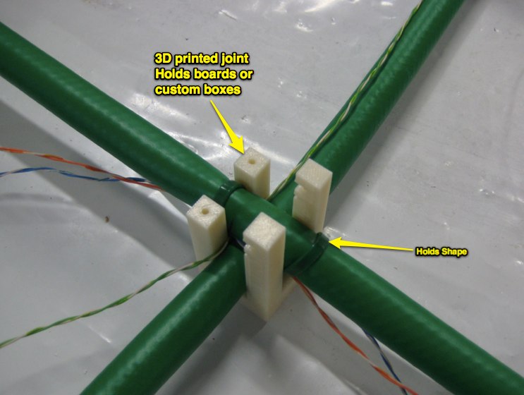
I already talked about the 3D piece, but I'd like to share something I learned while observing other structures and comparing them to my previous designs. I used to define an ovni shape to hold all ropes. This is an error. There is a lot of tension on that kind of pieces that make them quite easy to break.
I learned using park made by Corocord that all joints are created of stainless steel to withstand all tear and wear. I decided to change my design, to use some zippers provisionaly for the moment as the supporting element and free the 3D part of mesh tensions. In this way, I'm trying to prevent excessive forces on any of the electronic components also. Here is my final piece.
Electronic Design
This was my first board with a ATMega and it's way more complicated to wire it together than with the ATTinys. Also I was constrained by several self imposed requirements:
- Design should be Arduino compatible
- I should be able to program it using a FTDI cable or ICSP header
- Given RS-485 module is connected to TX and RX, a jumper should be installed to allow programming over FTDI.
- i2c pins would be routed to allow daisy chaining of several different controllers
- Screwheaders would be used for external power and RS-485, to make it easy to support it once the modules are installed into the mesh.
- Both sensor and led should be in one of the sides to allow board proper placing and detection.
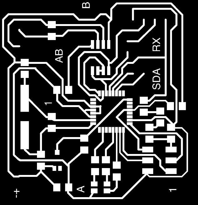
It was a real adventure to route this board. Eagle's autorouter best chance completed about 55% of the board. I decided to route it manually after 50 tries of auto/ripup and package placement.
One tip regarding schematic. When you use "add resistor" Eagle will locate resistor inside 01Sparkfun library. The default size for it is 0805, that's is a poor choice to jump traces. Try to use "add resistor1206" or use replace command to fix it. I discovered it thanks to my colleage Epifanio after board was ready to be milled. I had to spend an additional hour fixing it.
I still have to discover the proper way to add 0 Ohm resistor to the schematic. My method works, but Eagle displays lots of errors/warnings. file:schematictips.jpg
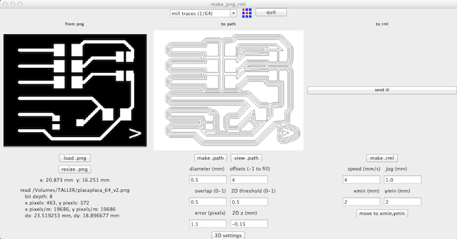
Milling the boards proved quite difficult also. It's quite easy to make a mistake, that the board moves in one of the stages, a broken drill (not sure about this), not drilled processor pads… All of those happened to me!!
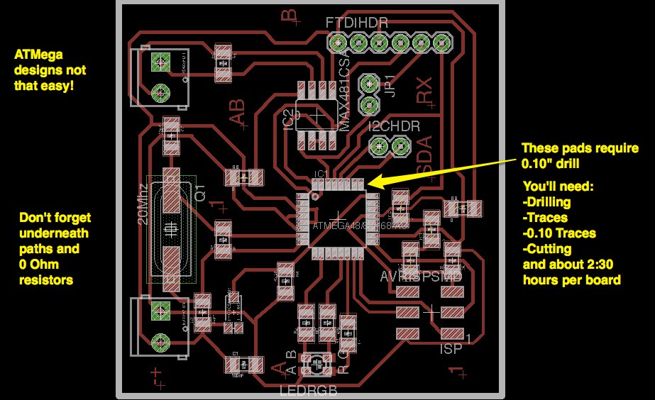
The 0.10" additional milling path once the regular traces job has ended is another good trick learnt from Epifanio. Here are the two files for each job. The white space around central area makes Modela to ignore it so you just drill on the area around processor.

Original Conclusions - Week 18
I'm quite happy to have finished my computer controlled machining, 3D printing and electronics design parts. There is lots of work on the programming part but I do really enjoy that kind of soft tasks.
Regarding what has not worked, logistics has been a big problem. We have not been able to configure our machine and my boards for some missing components. Once you get out of the inventory/basic arduino stock, every part imposes a week (or month) of delay or at least one lost afternoon. Digikey 24/48 shipping works wonderfully for US, but there is an additional five day delay when shipped to Spain. Most of Spanish electronic stores do not stock SMD and mixing through-hole and SMD it's quite hard. In my opinion is quite a waste of time, as there is a missmatch of standards in every piece you want to plug-in.
Milling the ATMega boards on the Modela has been a frustrating experience. It takes about 2-2:30 hours to create a new board and with so many steps it's easy to botch the process somewhere. My original idea is to create 25 boards, so I would need 62.5 hours just to mill the boards. Neither the cost por hour nor the materials (1-2 mills) suggest this is the right tool for this scenario. I will prototype a couple of boards and order the rest to a supplier online like BatchPCB. I plan to include comparison on ROI in my project description.
The CNC and HP Printer proved quite reliable albeit a bit slow. To create both clamps it took 6:30 hours. Given I would need 22 addtional ones, I would need to investigate other tools or methods like molding and casting.
Having a definite goal has allowed me to focus on all kind of real problems to solve, learning lots along the way, but the time frame hasn't allowed me to explore them in detail.
I plan to develop this project further during the summer/autumm, to be able to fulfil my dissemination plan.
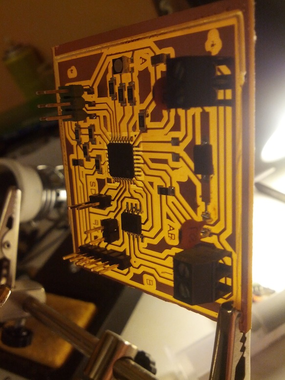
Completing the board
I received most of components just a few days after the final presentation and I was able to assemble the final board shown here in all its brightness:
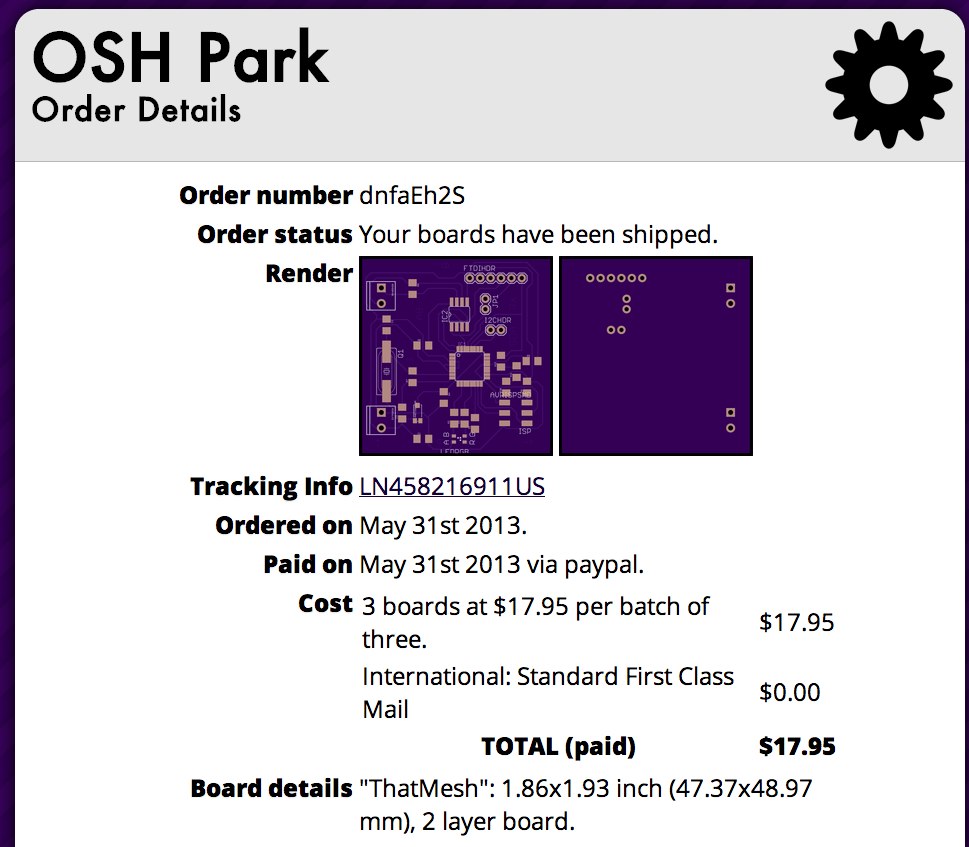
Because of the time requirements explained in the original conclusions, I decided to order three aditional PCBs from BatchPCB. I discovered BatchPCB was sold from SparkFun to OSH Park, a quite reputable PCB creation service based in USA. I made my order on 31st May.
Logistics nightmare
As days were passing by I was expecting a couple of shippings for the Texas Instruments DS17576s and the PCBs. Luckily, I got my tracking numbers so I could check in real time the order status. I got a pending delivery message from FedEx that was stalled on Madrid. As I asked them, they explained me that van was stolen and all contents lost! I contacted TI and they shipped them again, adding a considerable delay.
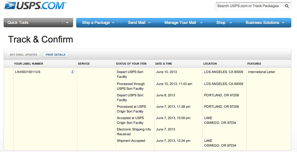
I was not so lucky with my OSH Park shipping. Order was placed on 31st May and shipped using USPS International Letter on 7th June. Once it departed Los Angeles on 10th June, track is lost. Usually it can take 3-4 weeks (up to 6 sometimes) but I cannot ask for refunds or lost goods up to 8 weeks, and nothing is waranteed given it's an international package.
Given I've not been able to have other boards, it's been impossible to develop my original plan of four boards further forcing me to pivot to other simpler options.
Pivoting, as Neal said
During project development class, Neal explained how manage your time to develop your project based on external demands or constrains. In this case, logistics and the deadline impossed some new constrains to develop the final project presentation. Even though I plan to continue developing the play mesh after FabAcademy I realized I need to focus on delivering a project fast that was fit to evaluation criteria. Instead of exploring future options and development, I had to focus on what I had, instead of on what I had not.
I decided to stuck to Anna guidelines for project evaluation: use an aspect of physical design, program the code, including I/O devices and designing and producing the boards. I would reuse the 3D parts to hold the boards, create a fabkit, create a custom I/O board using the LED and phototransistors I already had and then program fabkit to run Guacamole game as explained during the first week presentation.
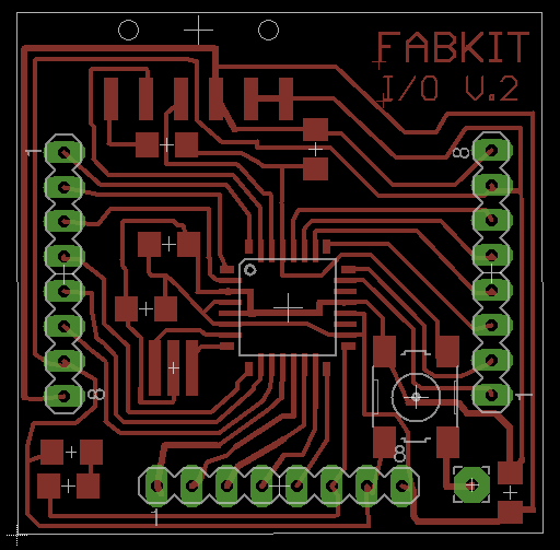
This is the Fabkit board:
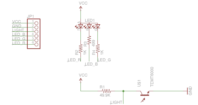
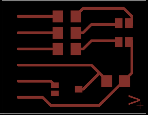
My I/O board was designed using Eagle and it includes a 6 pin header, a RGB LED and a phototransistor. As I'll try to match colors from previous assignments I will use just a pin for R, G, B and Y instead of running them all. These boards should fit on top of the 3D printer parts. This is the design and schematic:
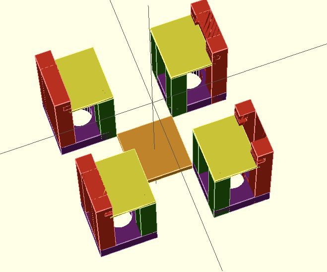
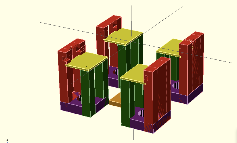
I included a virtual PCB in my OpenSCAD pieces to try several different arrangements. This is my final 3D arrangement:
This is the code that runs the Guacamole, once the Fabkit has the Arduino Bootloader. It uses a random function to select one of the pads that remains active until phototransitor triggers a change. This can be considered as a fast proof of concept or dirty hack, calling for proper refactoring using vector and other suitable data structures.
/*
  Final project - FabAcademy 2013 Cesar Garcia

 Play a Guacamole game using 4 phototransistors as sensors and 4 LED
 Note: Yellow is achieved activating a single pin and both inputs for the R and G pins are connected in a separate breakout board

 */

const int analogInPin0 = A0;  // Analog input pin that the phototransitor is attached to
const int ledPin0 = 3; // Digital output pin that the LED is attached to

int sensorValue0 = 0;        // value read from the phototransistor

const int analogInPin1 = A1;  // Analog input pin that the phototransitor is attached to
const int ledPin1 = 4; // Digital output pin that the LED is attached to

int sensorValue1 = 0;        // value read from the phototransistor

const int analogInPin2 = A2;  // Analog input pin that the phototransitor is attached to
const int ledPin2 = 5; // Digital output pin that the LED is attached to

int sensorValue2 = 0;        // value read from the phototransistor

const int analogInPin3 = A3;  // Analog input pin that the phototransitor is attached to
const int ledPin3 = 6; // Digital output pin that the LED is attached to

int sensorValue3 = 0;        // value read from the phototransistor

int activeButton=0;

void setup() {
  // initialize serial communications at 9600 bps:
  Serial.begin(9600);
  // Configure my led pins as output pins
  pinMode(ledPin0, OUTPUT);
  pinMode(ledPin1, OUTPUT);
  pinMode(ledPin2, OUTPUT);
  pinMode(ledPin3, OUTPUT);
  }

void loop() {
  if (activeButton == 0) {
    digitalWrite(ledPin0, HIGH); //If this button is active, light it up
    // read the analog in value:
    sensorValue0 = analogRead(analogInPin0);
    //By default phototransistor output 1024. When covered they return values between 600-800
    if (sensorValue0 < 800) {
      digitalWrite(ledPin0, LOW); //If light is covered, then light should be turned off
      activeButton=random(1,3); //Switch to another button
      }
    Serial.print("sensor0 = " );
    Serial.print(sensorValue0);
    // wait 2 milliseconds before the next loop
    // for the analog-to-digital converter to settle
    // after the last reading:
    delay(2);

  } else if (activeButton == 1) {
    digitalWrite(ledPin1, HIGH);
    sensorValue1 = analogRead(analogInPin1);
    if (sensorValue1 < 800) {
      digitalWrite(ledPin1, LOW);
      activeButton=random(2,3); //Switch to another button
    }
    // print the results to the serial monitor:
    Serial.print("sensor1 = " );
    Serial.print(sensorValue1);
    delay(2);

  } else if (activeButton == 2) {
    digitalWrite(ledPin2, HIGH);
    sensorValue2 = analogRead(analogInPin2);
    if (sensorValue2 < 800) {
      digitalWrite(ledPin2, LOW);
      activeButton=random(0,1);
    }
    Serial.print("sensor2 = " );
    Serial.print(sensorValue2);
    delay(2);

  } else if (activeButton == 3) {
    digitalWrite(ledPin3, HIGH);
    sensorValue3 = analogRead(analogInPin3);
    if (sensorValue3 < 800) {
      digitalWrite(ledPin3, LOW);
      activeButton=random(0,2); //Switch to another button
    }
    Serial.print("sensor3 = " );
    Serial.print(sensorValue3);
    delay(2);
  }
}
Final conclusions
Creating a whole project has enabled me to learn and experience lots around digital fabrication. Now, I know the virtues and limits of most pieces of equipment. I've also learnt why it's so hard to scale up these kind of processes and why some of the original manufacturers of reprapable printers have moved from the self 3d printable parts to lasercut based designs. I've also been able to learn about logistics and what a meaningful impact they can cause on these complex projects.
Looking back to my initial proposal, I think it was very ambitious and maybe outside what's expected as a final project because of the costs and development time. In any case, I plan to continue developing it and I think it's another lesson learned.
I feel I need more time to explore all these topics in detail, but I can say for sure, I've discovered countless paths to explore, enjoy and share with others during FabAcademy.
I'd like to thank all my colleagues from the 2013 course, specially my friends at FabLab Leon and to all my teachers and instructors to support this learning experience.