Week 15 Assignments
Table of Contents
Week 15 Assignment - Machine design
For our group project weve decided to built a delta 3d printer based on Rostock model of Reprap project. Our plan is to document and enhance the design with fabable components, enhanced termal profile and even better looks.
Instead of the more common cartesian models (like Prusa or printrbot printers), Rostock printers use three axis to position the hotend in the space. Given the complexity of defining a complete toolchain to support this printer, we've tried to set some goals regarding the final output.
Goals
- Compatibility: We should be able to use the same programs and workflow as with the other printers in lab. Instead of writing custom firmware from scratch, we will select one that support all printer features (Probably Marlin RC2).
- Feedback: Given the open nature of the reprap project, we'd like to contribute back and enhance this printer opening the design process
- As Fabable as posible: We plan to use all fablab tools to build this machine, modifying the required parts to use inventory components (if possible).
- Well documented: This printer is quite new, so documentation is quite sparse. We aspire to create a detailed build process so it can be later on reproduced in other labs.
My tasks this week
- I've researched about the possibilities for the electronics and firmware combinations. Our current choice is a SMD version of Generation 7 electronics plus Marlin Firmware. Repetier-host is also an alternative as supports rostock printers from scratch.
- I've contributed to the assembly of the printer, as well as locating printable versions for several componentes like the T2.5 pulleys (40 teeth) or the bowden mount for the Rostock printer.
I will describe the mechinal components and assembly process in more detail below.
Mechanical componentes
This printer works using three axis to move a carriage precisely over a fixed hotbed. It's the opposite mechanism as in Makerbot Thing-o-matic, with a fixed hotend and a moving hotbed in the x,y axis.
Each axis is composed of two paralel 1 meter M8 stainless steel rods. Rods connect with printer parts on both ends and are secured by nuts and bols. Both parts are bolted to base and top pieces, created on the CNC on MDF (19mm), to offer a rigid frame.
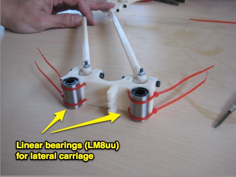
A carriage displaces along these axis, using to linear bearings (LM8uu). There are to arms connecting from the lateral carriage to the center one were the hotend is located. Movement is controlled by a NEMA17 motor attached to each base, using a T2.5 pulley that connects to the top using a belt. There is a ABEC-7 radial bearing on top, sandwiched by to M8x30 washers to prevent lateral desplacement on the belt.
To reduce central carriage weight, Rostock printers use a bowden system, where extruder is mounted remotely, and a teflon cable helps filament to reach the moving hotend. In this way weight goes from 600 to 60 g.
Assembly process
There photos describe the different parts and final position for each one.
The first part assembled was the base and three axis. Each axis requieres a base stand, a motor and a T2.5 pulley. Each axis holder is bolted to a larger base we milled on CNC.
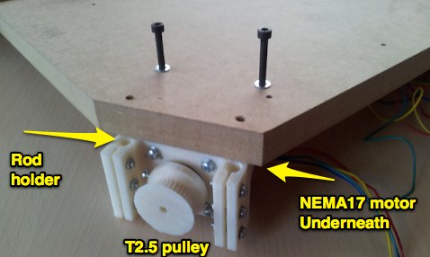
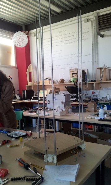
In this photo you can check the position of all vertical axis
Lateral carriage uses two linear bearings to move on the vertical rods
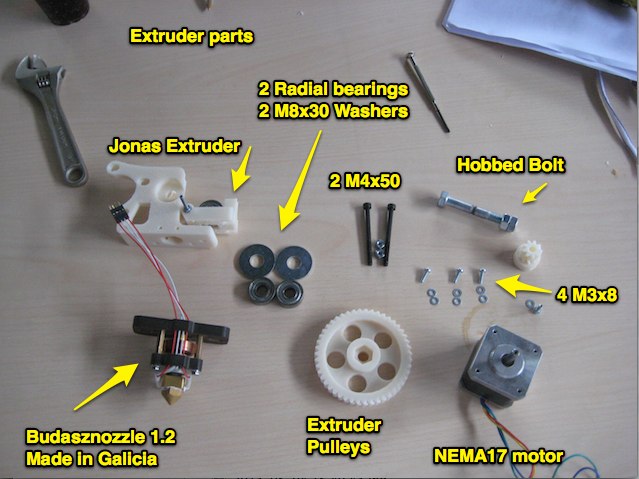
I was in charge of assambling the extruder. Here are the different parts:
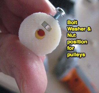
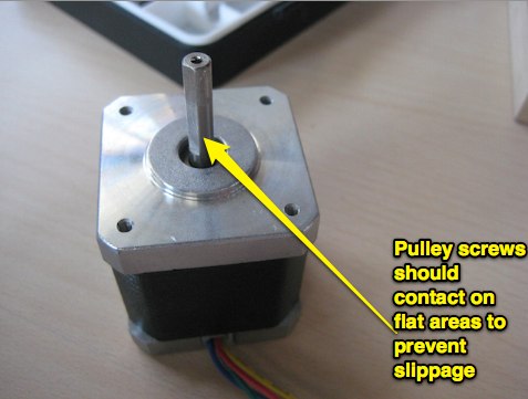
The proper way to connect pulleys to motors is to do it on the flat face of motor axis, using a washer to prevent excessive presure on the plastic.
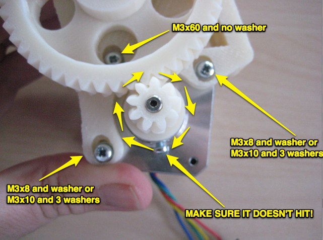
Here is the final extruder motor assembly
Our setup requires a bowden adapter, to push the filament through a teflon cable from extruder to hotend. Here are the components of the bowden adapter. Note, there are to hole sizes for 3mm and 1.75 filament. We'll be using the 3mm version, with a larger hole.
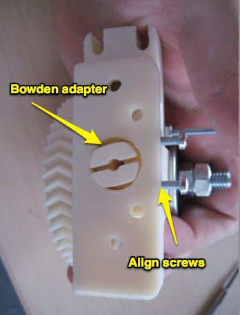
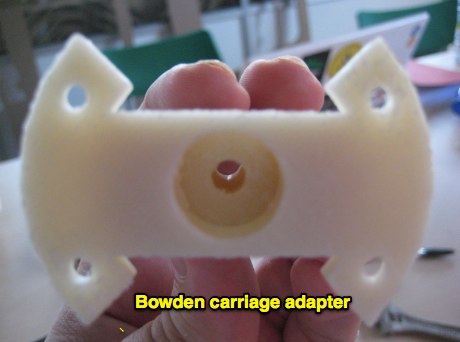
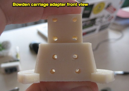
Central carriage assembled with bowden adapter on top and hotend below file:carriageall.jpg
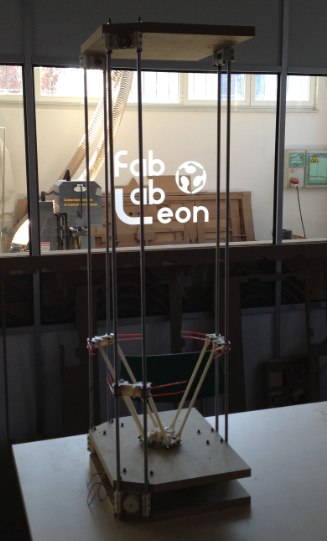
Our final mechanical setup, excluding lateral belts, that we're still waiting for:
