Module Moulding-casting
My 1st attempt: a moulded handortheses
My first idea for the moulding project was to make some kind of moulded custom orthese for a hand (eg custom ‘handbrace’). I discovered an Openscad program on thingiverse that should automatically make a 2 part mould from a STL file (http://www.thingiverse.com/thing:31581).

First, I made a 3d scan from my own hand, using Kinect and Reconstruct me( http://www.reconstructme.net/). The 3d scan came out pretty good, even Kinect only has a fairly limited resolution.
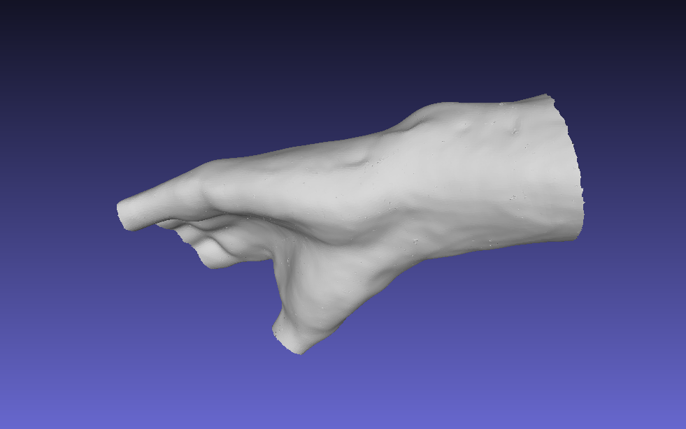
For 3d scanning I’ve worked a lot with structured light 3d scanning (David scanner, http://shop.david-vision-systems.de/product_info.php/language/en/info/p124_DAVID-Structured-Light-Scanner.html), but the downside with that is you’ve have to stop for every side that you scan and later on stitch all the individual scans together again. With Kinect Reconstructme you can just move the Kinect around the object in one slowly and steady movement and the scan is done.
Openscad
The mould generator in Openscad has some basic setting to set mould dimensions, place for pouringhole and alignmentpins etc. It then generates two moulding halves

The input needs to be a STL file. Comments on Thingiverse indicate that number of STL faces in Openscad is limited to about 10K, because Openscad can’t handle more. Mine is 100K, So I used Quadratic Edge Collapse Decimation in Meshlab for this. It gets ´blocky´in several places, but I’ll go with it. (I later on tried this mesh reduction with a trial of 3D Coat: that worked better and complety leaves original shape will reducing to 10K faces. But that software costs $350, and the trial doesn’t allow saving)
Challenges
When I started working with de reduced 3d scan and the Openscad program I soon discovered I needed to rethink what I was doing: I wanted to make a hollow object as an end result. Else I could not be worn around a hand. But the Openscad Mould maker is aimed only at making moulds for massive object, not hollow. So I somehow would need to reprogram it, and make it into a hollow mouldmakingmachine. As having fairly limited (poor?)programming skills, this would be a challenge. Also getting the scan properly aligned inside Openscad is rather cubbersome to work with, as is the speed due to the maximum facecount .
After taking things over with Amsterdam Fablab guru Bas Withagen, I abandoned the idea of doing something with a 3d scan. I’m here to learn about casting&moulding, and this would cost way too much time and leave no time to do actual Moulding-casting. Another time!.
My 2nd attempt
I decided to go for a more simple object to mould&cast. I still wanted to learn more from Openscad, and found another Openscad program. This one is a parametric wheel maker (http://www.thingiverse.com/thing:21486). It automatically generates a wheel, with configurable spoke-pattern, rim thickness and other features.

I decide to go for a fairly basic wheel and spoke pattern. Bas Withagen learned us that a interesting way to make moulds would be to first cast a flexibele (and negative) mould. And from that do the actual positive casts. The first ‘master mould’ would be milled from wax, and be a positive of the object.
More challenges
But, after trying to combine the Openscad wheel generator with the mould generator, all the output STL´s have serious problems. Even Netfabb cannot fixed these errors. The reason seems to be sequential use of STL´s in and out of OpenScad. Solution would be to join the two programs into one, but, as I mentioned before, my programming skills are too limited for that. So I’ve decided to revert back to drawing the mould in Rhino, to not lose any more time
Although I spend really quite some time in the first two attempts, this spent time is not ‘wasted’: I’ve learned quite a bit from Openscad.
Moving on……
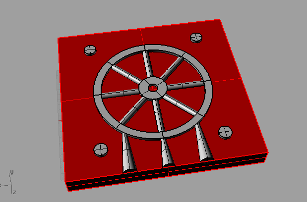
In rhino to make the master mould, two equal sized boxed were placed, symmetrically around the wheel. Also 4 alignment spheres are placed around it. These make it possible to align the flexible moulds halves later on.
To actually make the master moulds from this, Boolean operators can be used.
Steps necessary, dependent on type of moulding:
1.
Non-symmetrical mould halves
For one mould-half, take one box, and do a Boolean Union with the wheel, holes and the alignmentspheres

2. For the other mould-half, take the other box (hide the 1st), but now do a Boolean Union with the wheel and the pouring/air-holes only. After this do a Boolean Difference for the alignmentspheres. This makes half-sphered ‘holes’ in the mould. These will fit into the other half

For Symmetrical mould halves it’s even easier: just everything unioned together will be the mastermould. Make shure though that everything is exactly mirrored on x-axis! Else the two identical master mould won’t fit together. For alignment I used cilinders so I can use wooden dowels to align.
Prepare for milling
The master moulds will be milled out out of machinable wax, on a Shopbot CNC milling machine
After exporting the Rhino file to STL, the milling files needs to be setup. With the Shopbot Partworks software the setup is pretty straightforward. Apart from positioning the model to be milled, also the toolpath to be milled has to be defined, in terms of depth and speeds etc. Milling is done in two milling passes: one for rough milling (takes out rough geometry), one for finishing milling (takes out final geometry). The milling paths are then saved as a combined file and import in the Shopbot

Saving time….
I discovered that some decisions in the setup can sometimes lead to really bad results. I wanted to save time, I decided to do a rouhing pass only. Because Partworks doesn’t accept a rough pass only, but does accept a finishing pass only, I setup the finishing pass with the parameters of the rough pass. But when I loaded this file in the Shopbot and started the mill, the milling head suddenly dug really deep into the wax and started throwing the wax block around! It came off the underlying board completely and I had to quickly push the emergency stop. It later turned out that doing it this way, Partworks assumes that the rough pass already has been done, and starts the finishing just like that (pretty deep into the material). I decided to stop for the day and pick things up the following day.
Picking things up
The next day, after having learned what not to do, I readjusted all the Partwork settings to a combined rough and finishing paths. The milling only took 20 minutes for each halve. They came out pretty nice

Casting the flexible moulds
After this step, the wax master-moulds where each filled with Ooomo Smoothon 25. Because the room in which the casting was done was pretty cold, a couple off students here placed the moulds in the sun to cure faster. But that still took hours, as supposed to 75 minutes stated in the manual. I placed mine in a small convection oven at 150F/75C. After 1,5 hour the moulds where dry enough to take out. The resulting mould are smooth and have all of the fine details the wax mould has.


Casting the wheel
Because the two halves are symmetrical, I left the alignment areas as open places. My idea was to makes little wooden pegs, and use those to align. But because of time, skipped this step. And just placed the two halves on top of each other, aligning them by looking between and checking. With tape and two wooden boards I joined the two halves firmly together.

For the casting resin I used Oomo Smoothon 300. This is a super fast curing resin, and also its fairly ‘runny’ (liquid-like) . This is good, because my mould has fine and small details, and otherwise the casting resin would travel down the moulding hole properly. The curing took only 10 minutes, and resulted in a nice white colored plastic wheel.

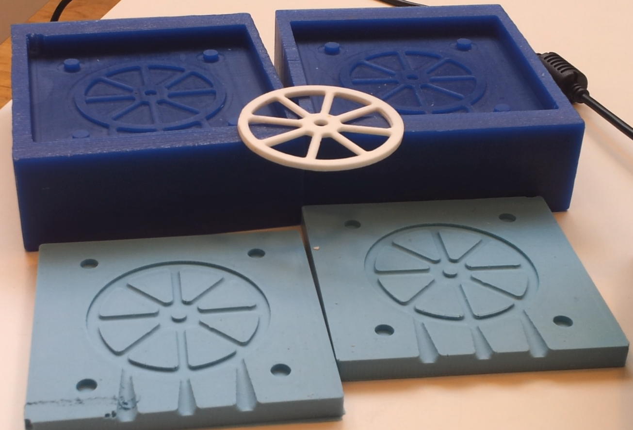
End result
All in all I’m pretty happy with the result. And best off all, because all the earlier attempts I made and challenges I had to overcome, I’ve learned a lot about moulding and casting!
Thanks Bas Withagen and rest of Fablab Amsterdam crew for their support during my Fabacademy week!