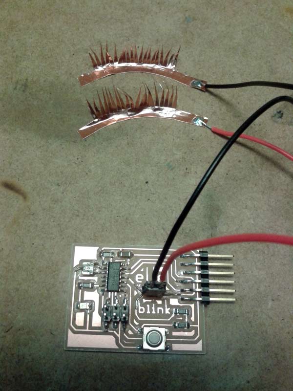
This week I made a visualization of the eyeBlink board that I built in Electronics design week.

The purpose of this board was to turn on the LED with a button, but also in my case, to turn on the same LED when you close your eye. To achieve this, I built an eyelash out of copper, so that you close the circuit when the two layers of copper are in contact, acting just like a button.
This week I wanted to read the times the eye was closed, and visualize the different rhythms involved in this action in a given period of time. So the starting point has been to read the data from this board. Since it wasn´t programmed to send data through the serial port it has been necessary to reprogramm it. I used ARDUINO IDE for this purpose. To be able to read serial communication with the ATtiny 45 used in this board, the SoftwareSerial Library was needed.
The final code to program the board:
#include
#define rxPin 0
#define txPin 1


SoftwareSerial serial(rxPin, txPin);


const int buttonPin = 3;     // the number of the pushbutton pin
const int ledPin =  7;      // the number of the LED pin
const int eyeBlinkPin = 2;      // the number of the eyeBlink pin

// variables will change:
int buttonState = 0;         // variable for reading the pushbutton status
int eyeBlinkState = 0;       // variable for reading the eyeBlink status

void setup() {
  pinMode(rxPin, INPUT);
  pinMode(txPin, OUTPUT);
  serial.begin(1200);
  serial.println("ATtiny45 Software serial");
  // initialize the LED pin as an output:
  pinMode(ledPin, OUTPUT);
  // initialize the pushbutton pin as an input:
  pinMode(buttonPin, INPUT);
  // initialize the eyeBlink pin as input:
  pinMode(eyeBlinkPin, INPUT);
}

void loop(){
  // read the state of the pushbutton value:


  buttonState = digitalRead(buttonPin);
  eyeBlinkState = digitalRead(eyeBlinkPin);

  // check if the pushbutton is pressed.
  // if it is, the buttonState is HIGH:
  if (buttonState == LOW || eyeBlinkState == LOW ) {
    // turn LED on:
    serial.write(1);
    digitalWrite(ledPin, HIGH);
  }
  else {
    // turn LED off:
    digitalWrite(ledPin, LOW);
  }
}
After this I made some testing opening the serial monitor in ARDUINO and reading the serial monitor in PROCESSING, confirming that either when I press the button or touch together the copper eyelashes the serial monitor was reading the number 1.
This is the code to read the serial in PROCESSING:
// Example by Tom Igoe

import processing.serial.*;

Serial myPort;  // The serial port

void setup() {
  // List all the available serial ports
  println(Serial.list());
  // Open the port you are using at the rate you want:
  myPort = new Serial(this, Serial.list()[0], 1200);
}

void draw() {
  while (myPort.available() > 0) {
    int inByte = myPort.read();
    println(inByte);
  }
}
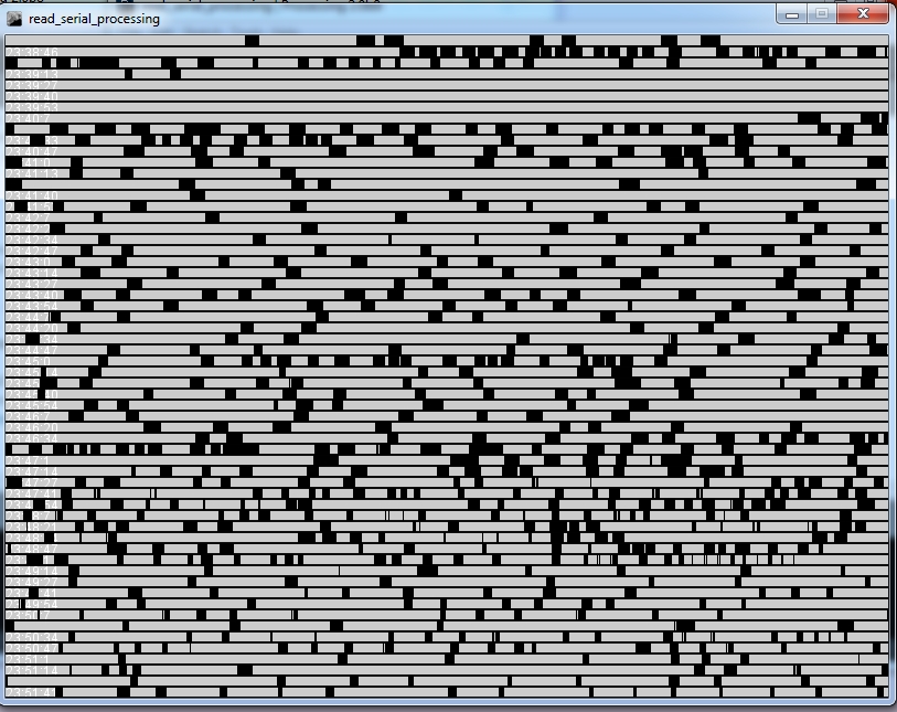
Once I was reading the input from the board, I designed the next code to visualize the rhythm of the pulses coming from the eye blinking. The idea is to draw black squares in each blinking, and a line when not. This creates an easy way to visualize the rhythm involved:
//eyeBLINK visualization by JAPI

import processing.serial.*;

Serial myPort;  // The serial port
int col = 0; // starting point of the lines on screen in X
int row = 10;  // starting point of the lines on screen in Y


void setup() {
  // List all the available serial ports
  println(Serial.list());
  // Open the port you are using at the rate you want:
  myPort = new Serial(this, Serial.list()[0], 1200);
  size(800,600);
  smooth();

}

void draw() {
  if (myPort.available() > 0) {
    int input = myPort.read();
    println(input);
    line (col,row,col,row-10);
    col = col+1;
    if (col > 800){
      col = 0;
      row = row + 10;
    }
  }
  else {
    line(col,row,col,row-1);
    col = col+1;
    if (col > 800){
      col = 0;
      row = row + 10;
      text(hour()+":"+minute()+":"+second(), col, row);
    }
  }
}
The code also prints the current time when the drawing reaches the beginning of a new row.
The code in action:
And a screenshot after one sheet is completed:

In this sheet you can analize in wich time you have been blinking more constantly, faster or slower; even when your blinks were longer or shorter, in a concrete period of time.