This week I took the pieces I had 3D modelled in week 2 assignment(Computer aided design) for the wire mask, as the starting point to start 3D printing in the 3D HP Designjet we have in FabLab León. The first piece I want to print is the one shown bellow:
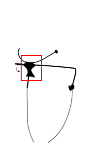
I want to check how accurate the printing is, and also I want to place it in the space between my eyebrows to see how it fits and how precise is the method that I used to model my head; and so forth to decide if it is necesary to scan that area to achieve an even more accurate 3D model.
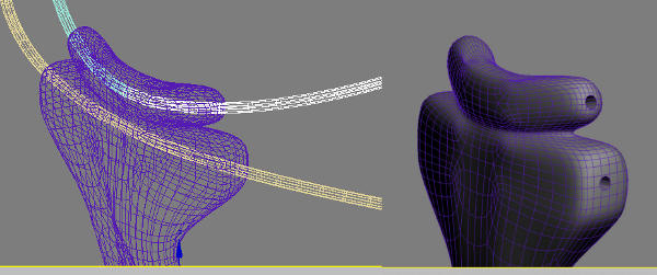
Before printing the model, I made the holes of the 1 mm aluminum bars that I will use. I continued using 3D Studio Max for this porpuse, using proboolean tool:
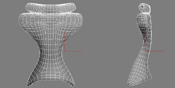
And this is the final result of the piece, in a front and side view:
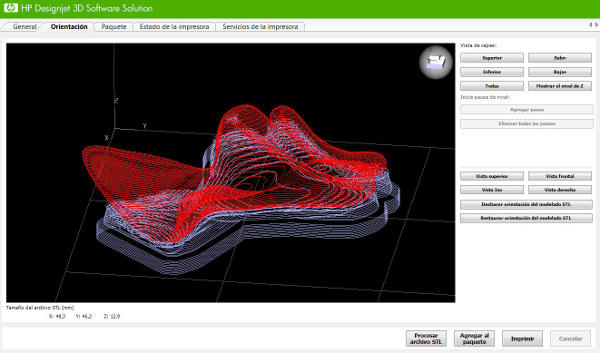
I exported the piece with stl format, and before taking it to the HP software, I opened the file in rhino, just to check the size and the mesh. Once in HP software, I imported the file and let the soft to automatically rotate the piece, to minimize the support material needed for the printing. The accuracy used is 0.25 mm. Bellow is the preview with the lines of ABS material in red and support material in blue:
And now, time to print!!
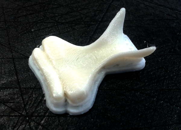
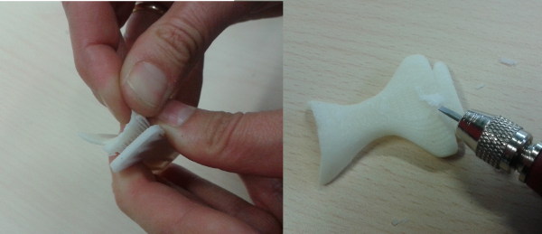
The result was very good, I was quite surprised with the accuracy of this machine, the layers of ABS are very very tiny. Before it gets cold, is good to remove the support material. Most of it you can do it with your fingers and nails, though I also needed a srewdriver as shown in the picture bellow:
Testing the piece in my head was great at first, since it fits perfectly in the space between my eyes. But after the first excitement, I realized that the piece should be placed lower, and that it is actually too bended to fit perfectly in its place.
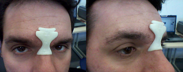
As a conclusion i would say that to 3D model a piece like this, it is needed an accurate 3D scan of the area to get a perfect result. By the way I have to say, that I´m very happy with this step result.
I also 3D printed another version of the wire mask, shown bellow:
For this version I printed the joints of the 1 mm aluminum bars, following the same steps. Taking the model from week 2 assignment, I made the holes with the proboolean tool:

Then printing and cleaning the pieces

As second part of this week assignment we have to 3D scan an object. My porpuse is to scan my head, or at least the area I am focusing on: the eyes and forehead. My first attempt has been to try 123D catch Autodesk web platform. This is an image based processing to turn photos into 3D models. I took several pictures of myself, with a friend´s help, shown bellow:
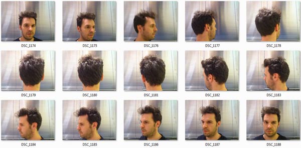
This was a complete failure because I rotated instead of the camera. So what it seemed to be a very good Idea was actually a very bad one since the object that you are going to photograph has to be still, and the one who is taking the photos has to move around. So here is my second attempt:

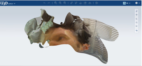
This time I focused in the area of the eyes and forehead, taking close up pictures. Again this didn´t work properly, since 30 or 40 pictures are needed to achieve a good result, and you also have to take pictures of the whole object, and only after that, if you want to have a more detailed area, you can take close up photos. The result was the one that follows, it creates a mesh, but as you see, head shape less:
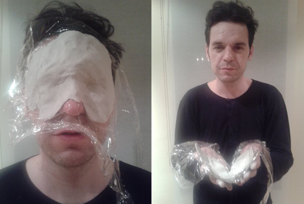
After these two attemps, I came up with another idea, this was to create a mold of my head, so that I can scan it in the modela pointer scanner. As molding material I used a air-hardening modelling product, wich I spread out my face and let it harden for around 12 hours:
Once the mold was hardenned I placed it in the Modela scanner The scan precision I used was 1 mm for X, Y and Z axes.
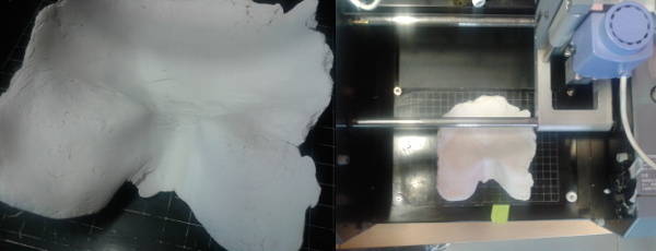
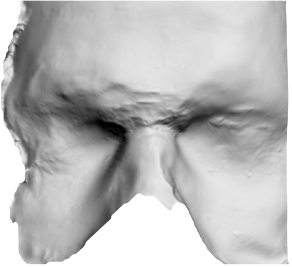
It took around six hours to complete the scan, but the result was really owesome!! it is a more than enough 3D model of the eyes, eyebrows and forehead. I exported as a stl format, and then I openned it in rhino to view it and also to clean up some vertex.
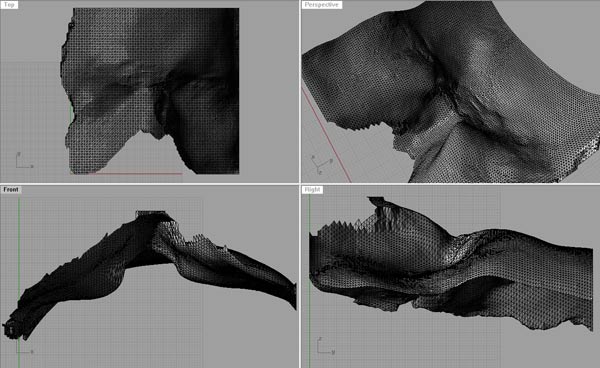
I will use this 3D mesh to remodel the pieces that will be placed in the area between my eyes, so that they fit perfectly. I will use these new versions in the molding and casting week assignment to produce them in a soft material like silicone, since it will be in contact with the skin, and the whole device gets much more comfortable.
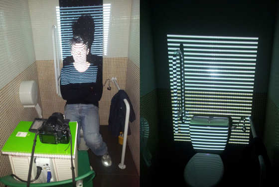
In collaboration with Ruben Ferrero a FabAcademy pal in FabLab León, I 3D scan my head with the Video Projector approach. We followed the instructions of this Instructables page, and we set up the capture room in the toilet of the FabLab, since it was the only dark room there. There, we used a projector to project the three patterns in to our faces, and then we took one picture for each pattern.
From the Download page we chose the ThreePhase-1-applet.zip , as the Basic three phase decoder application wich runs in the browser, and we replaced the pics inside the img folder, with the ones of ourselves. Then run index in the main folder and the processing program takes your pics from that folder.
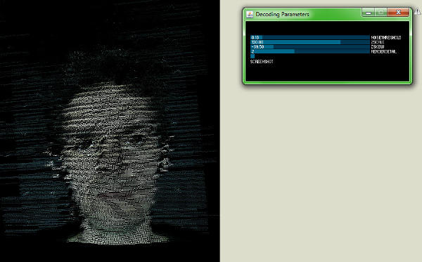
Next step was a little bit tricky, since when the app promps the face is not well orientated, and the sliders behaviour is not very friendly at first. After playing with it, we suggest not to touch anything but the ZSKEW slider to get the face well orientated. Once this is done the behaviour of the ramaining sliders is obvious. Here I show you a close up of the point cloud generated by the app.
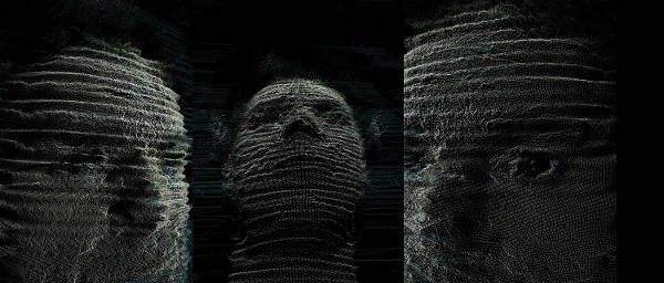
As you can see in the image, the accuracy of the scanning is not very good, considering that you get some wave shapes in the surface. So as a conclussion I would say that this is not a good approach to 3D print the result mesh but a fantastic and funny procedure for image processing, even working in real-time videos.