Week 9:Computer controlled machining
This week I wanted to make the inner frame of the cycle trainer/racing rollers machine for my final project.
This frame needs to bear and position accurately 3 rollers which will support the rider and bike plus the speed sensor and device to create resistance on one of the rollers. To achieve this it needs to be stiff, strong enough to support up to 250dN [3* (bike +rider)] of shock loads and be sufficiently accurately built to allow the rollers to be aligned correctly across the frame. I selected 12mm ply for the frame material as I believe it has the correct lateral strength for the load bearing, would be sufficiently stiff when braced, durable and not too heavy.
 My first task was to complete the conceptual arrangement of the design. I started this in FreeCAD earlier in the course. Whilst the basic elements had been drawn, I now needed to ensure the parts were accurately dimensioned and to add stiffening structural elements.
The next requirement was to add details of the joints. I experimented with adding finger joints in FreeCAD. I found it difficult to make quick progress without creating tremendously complex drawing components comprising many small joint elements. I was also concerned about exporting the results to the ShopBot. I tried exporting one part as an *.stl file and reading it into SketchUp and found I could not see the result. These concerns about detailing the design in FreeCAD prompted me to produce the cutting paths outlines in another software package.
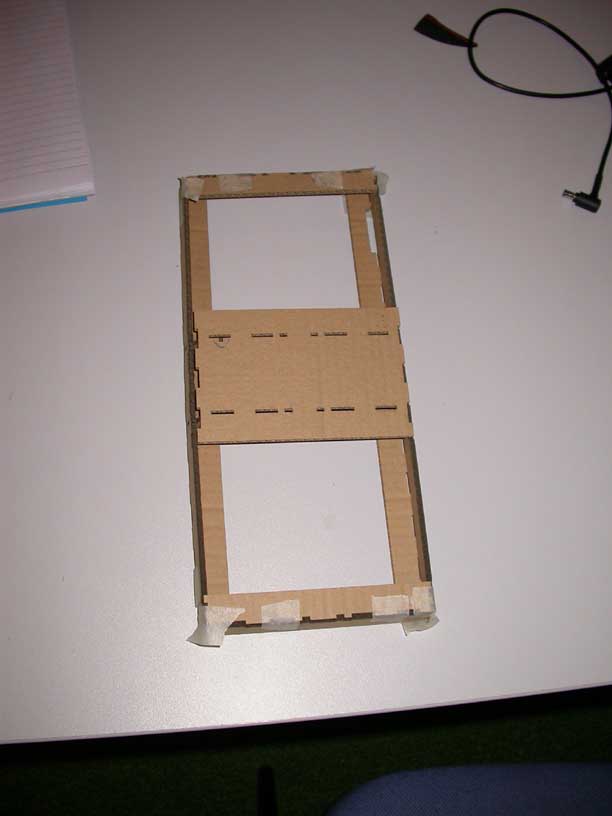
The detailed cutting paths were made in Inkscape. It was particularly important to check the detailed parts for fit as they were not derived directly from the 3D arrangement; rather they were re-drawn in 2D. I scaled the large design down by a factor of 5 and cut it in cardboard on the laser cutter. The first scale model highlighted 2 errors in placement of joints which I corrected. Joel also advised me to reduce the number of fingers in the long joints to aid assembly. I cut a second scale model and found the new design to be correct.
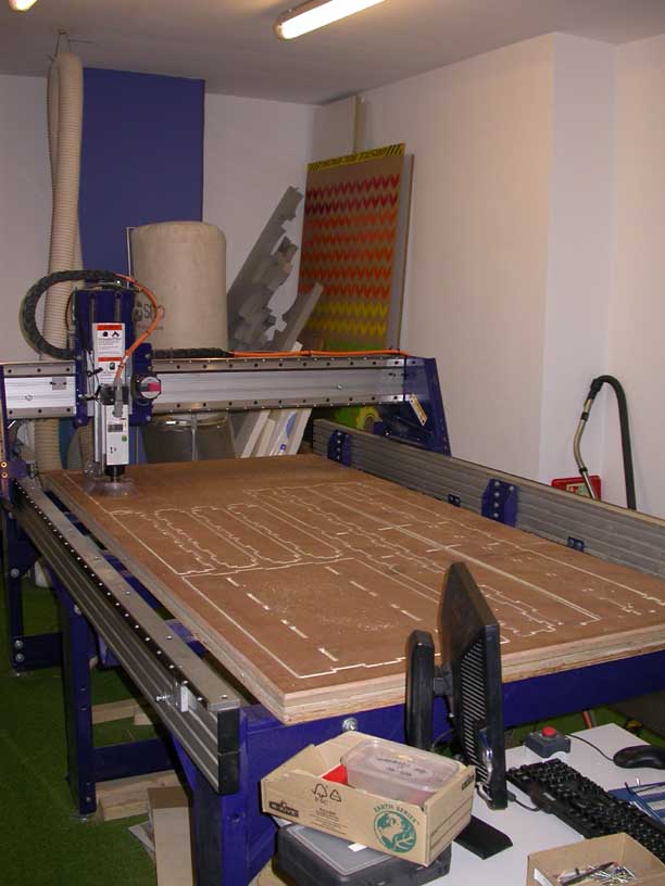
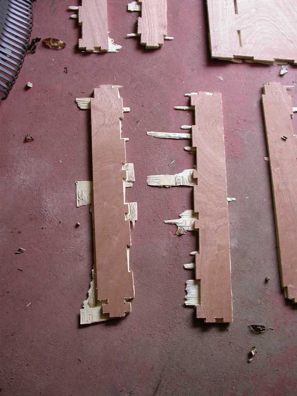
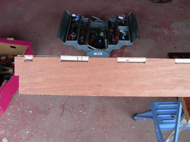
The Inkscape files were translated to *.dxf for the ShopBot and I added fillets and prepared the files for cutting. A sheet of 12mm apply was fixed in place and cut. Two problems became immediately apparent. The plywood sheet was warped when freestanding. Although we attempted to eliminate this when fixing to the ShopBot, in the cutting process the restraint provided by the fixing screws diminished as the cutting progressed. This caused many of the cuts not to be deep enough despite the programmed cut depth being theoretically sufficient. Secondly the design of the finger joints is problematic. The build up of tolerances over 1.7m length is leading the joints to be misaligned. This could be a result of designing each part separately in Inkscape and not using exploded parts from a unified 3D design and/or general tolerance build up.
As a result the construction of the frame is not complete yet. My next step is to redraw the detailed designing SketchUp in 3D and then explode the parts – a technique Joel has shown me. I will modify the finger joints on the long joined edges and create test pieces before committing to the final cut. I will also create fixture points in the cutting path layout to restrain the pieces more effectively in cutting.
Update 09/04/13
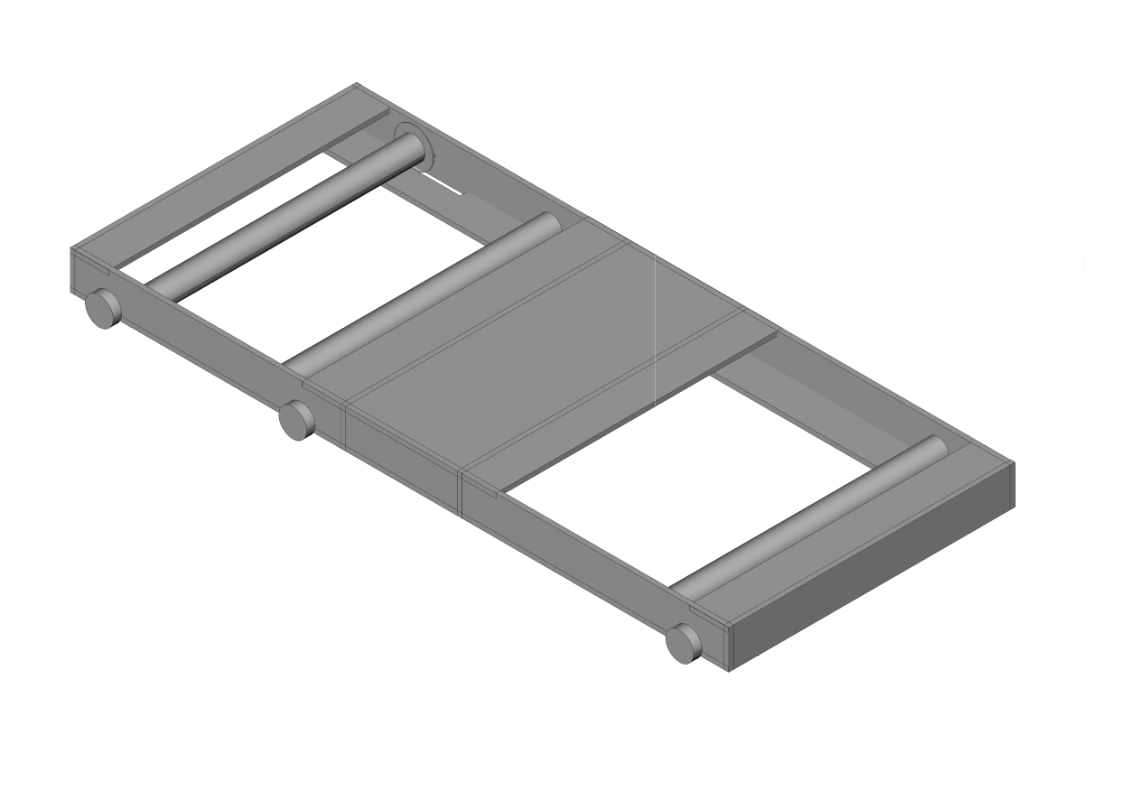
The rollers frame was re-designed to be simpler and to have less jointed lengths. I also completed the whole design by including the rails and wheels to allow the roller carriage to move backwards and forwards.
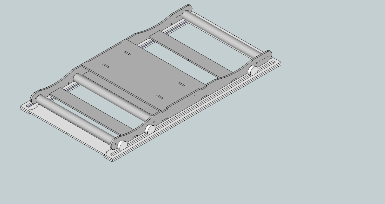
I used SketchUp to complete the design. Once the 3D assembly was designed, I copied the surface shapes I needed to cut on to a 1220*2440mm surface to be cut on the ShopBot. I also ensured there were sufficient sites on the cutting sheet to fix it properly to the ShopBot bed in order to prevent the poor cutting experienced in the first attempt.
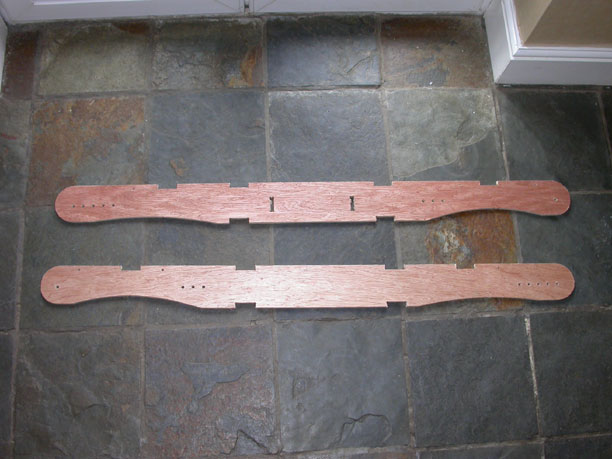
Several tool paths were designed in Partworks with 2 drilling paths needed for the fixturing holes and another for some 6mm holes which were part of the design, in addition to the end mill paths for inner and outer surfaces. The resulting cut quality was vastly improved despite the plywood used being very warped.
Most of the joints needed to be cleaned and eased by hand, but assembly was straight forward. There are several points in the fundamental design that need attention at this stage before the rollers will be fully functional.
Update 22/05/13
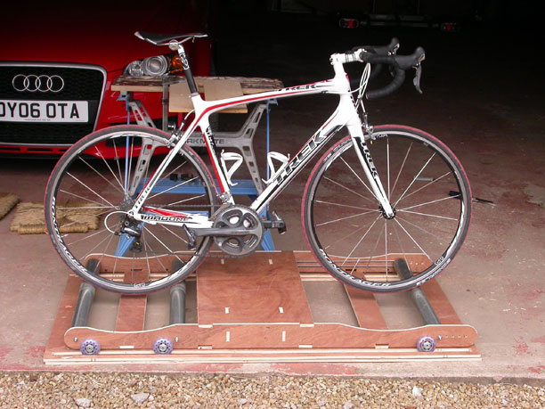
I modified the rollers spacings to improve the support for the bike and to allow the drive band for the front roller to operate at the correct tension. The front roller was positioned too far away from the middle roller. I did this using a hand drill making holes at 25mm intervals and experimenting until I found a satisfactory arrangement.
Once I had this, I modified my original SketchUp design and recut the side plates on the ShopBot. I need to cut two further cross stretchers as they now need to be modified.
I also designed a carrier which will sit on the rear roller for the magnet needed for the Hall sensor to detect the speed of rotation. I produced an stl file which is awaiting the 3D printer.
Next steps are to re-assemble the modified design and mount the circuit board and magnet. Further work is also required to improve the Processing sketch which measures progress in the race.