Week 6: Electronics design
My final project, cycling rollers, requires a method of sensing the rotational speed of one of the rollers. Typically speed sensors on cycles work by detecting the passing of a magnet attached to a spoke on one of the wheels using a Hall Effect sensor or a reed switch. I intend to use a similar principle to determine the “road” speed of the rollers by placing a magnet on one of the rollers and counting the number of rotations in a known time. As an initial step towards this, I want to establish that I can use a Hall sensor in this way by having it illuminate an LED as it passes. This feature will be incorporated in the final design to allow a user to determine the speed sensing is operational and will allow me to start developing with the Attiny44.
Current limiting resistor
The first step in the design was to select the current limiting resistor for the LED. Once I understood that the maximum allowable current was 40mA and that a voltage drop of 1.8V was needed across the LED a minimum 80R resistor was needed. I mistakenly believed that a 10K resistor could be used as I did not initially understand that a current of order of 10mA is needed for the LED to illuminate. Ohms law indicates a resistor around 320R, hence the selection of 500R.

Hall Effect sensor
I reviewed the data sheet for the Allegro A130x series of Hall sensors in the FabLab inventory and determined they were suitable for my need. One feature of their operation was the output signal was centred on Vcc/2 swinging up to Vcc and down to Gnd depending on the polarity of the magnet passing the sensor. This meant that I needed to use an Analogue to Digital Convertor on the Attiny44 to read the input signal which in turn determined that a bit on Port A would be required for the input signal. I reviewed the data sheets for the Hall sensor and the Attiny44 and determined no further external circuitry was needed to connect the two devices.
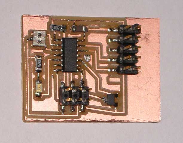
Circuit board design
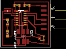
Having become familiar with Eagle following the tutorials on Sparkfun, I drew the schematic for my circuit. Once I had inputted that, I used the auto-routing feature to layout the board traces. I found that I could eliminate the need for any jumpers by utilising a combination of Port A pins which I finally selected. I cut the PCB using the Modella and mounted the components on the board. I found the resonator particularly difficult to mount as I could not be sure solder had flowed underneath it. I managed to lift a copper track through overheating the board whilst doing this, although it was not broken and did not need repairing. Mechanically it is held in place as the resonator has 3 contacts holding it in position.
Programming the ATtiny44
Once the board was checked I programmed it using the FabISP. My programming experience is limited so I elected to use the Arduino compiler to ease this process. As a test, I first programmed the controller to blink the LED on and off every second.
The next step was to establish the controller was reading the Hall Effect sensor by reading the ADC output in a serial data stream sent to my computer. This was successful and showed a stream of readings averaging 512 corresponding to Vcc/2 as expected, changing when a magnet was passed near the sensor.