Week 15 Machine Design
For this week’s task I have elected to make a pan tilt head for a camera tripod. The intention is that I should be able to direct my camera remotely to allow me to take pictures of wild life etc.
The outline specification for the device is:
Hardware
- Support a DSLR in landscape or portrait orientation
- Pan and tilt centred on the focal point of the camera
- Movement:
- Pan 360 deg
- Tilt 270 deg
- Fits to my (standard?) tripod
- Battery powered
- Smooth pan and tilt for video
- Clearance for 300mm lens
- Appearance
- Showerproof design
- Electronics enclosed
- Aesthetically pleasing
User interface
- GUI to be a small canvas running concurrently with the Canon software which displays the image to be photographed and enables remote triggering of the shutter.
- Control by use of direction arrows and/or touchpad/mouse control
- Controlled via a single usb cable 5-10m long
- A USB hub will be needed as an interface is required for both the pan tilt mechanism and the camera control

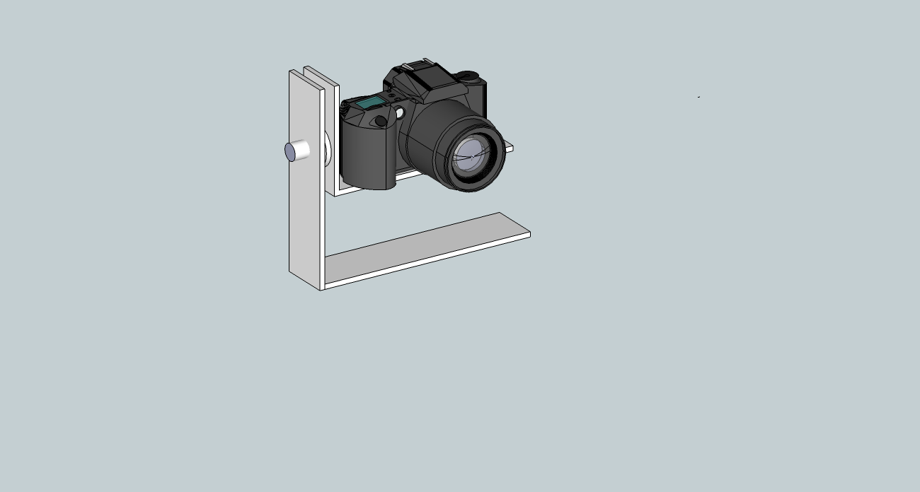
I have drawn a concept layout for the machine on SketchUp. I am intending to manufacture the components from sheet acrylic or HDPE for laser cutting/milling or to cast components which it is not possible to make this way. I am currently working on the detailed design. Key considerations are the selection of the bearings, plastic rod for hinging the rotation of the joints, mounting of the drives, the manufacture of the gears for the driving the arms and ensuring the structure is stiff enough to support the weight of the camera adequately.
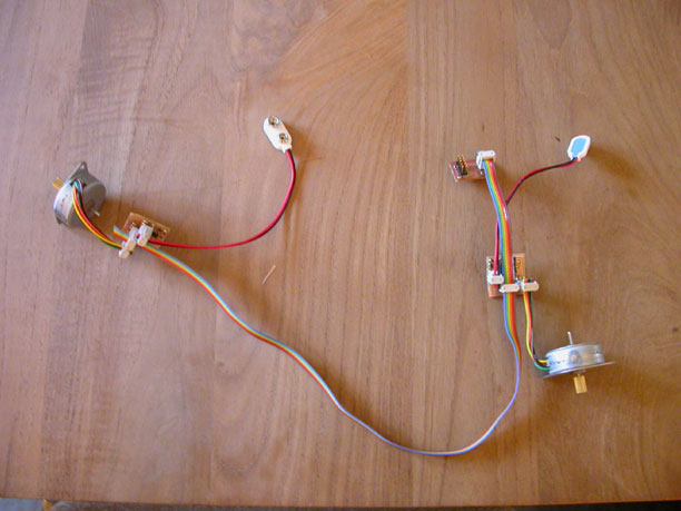
I elected to use 2 unipolar stepper motors to allow accurate smooth movement and a straight forward control design. I will make use of the 2 pins on Port A of hello.stepper’s ATtiny44 which are connected to the 2*3pin header for communications. I have built the boards and am in the process of modifying the code to suit. I have also made a simple circuit board to bridge between the FTDI header and the 2*3 pin plugs needed for the hello. stepper boards. If possible, I intend to replace the bridging board with one that allows a direct interface to USB.
Update 22/05/13
Components design and manufacture
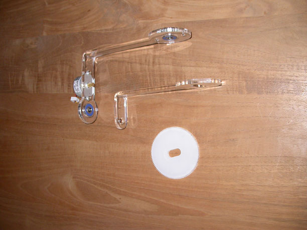
I decided to manufacture the two main arms for the pan/tilt mechanism from 6mm sheet acrylic. I believe this material has the structural stiffness I require. I projected 2D shapes for the arms from the 3D arrangement in SketchUp and prepared them for cutting on the laser cutter using the SketchUp DXF export plug in. The line widths were modified for cutting using Inkscape and then the shapes were exported as PDFs. The PDFs were “printed” to the laser cutter. The arms were bent to form 90 degree brackets by heating for 30 seconds with a heat gun with a strip heating nozzle. The bends were guided with some formers made from wood off cuts.

The drive gear shape was also drawn in SketchUp using a plugin called gear.3.rbs. I chose a pitch diameter for the gears that allowed the motor to be mounted on the outer swinging arm oriented vertically. This resulted in a 110T gear and 11:1 drive ratio. The gear was cut from 3mm acrylic sheet, which was selected for its ease of accurate cutting and hear wearing surface. On inspection of the first gear I made, I decided to offset the cutting path by 0.1 mm in the SketchUp design and re-cut as I found the teeth were too pointed for correct meshing. This is a result of the acrylic melting away from the cut line. It should also be noted that the tooth surfaces are not perpendicular to the gear face as the material melts more on the upper (laser side) surface when cut.

I also purchased two ball bearings for the pivoting arm assemblies.
Bushes for pivoting the arms were also designed in SketchUp and prepared for 3D printing. As they are non-structural complex shapes, I felt that 3D printing was the most appropriate method of manufacture. The stl files are currently waiting free time on the printer.
Code
The C code and Processing interface are also under construction. I used the hello.stepper code to test the two stepper control boards and they both functioned correctly. The next step in the C code development was to read in an integer from the serial port of my computer and step the desired number of steps. This is now also working. I used the serial communication get char void used in the Output Devices week’s examples. I needed to modify the char variable to be an 8 bit integer as my first attempts were made reading ASCII coded characters. Next steps will be to add the ability to recognise a node identifying character as the serial stream will share carry commands for two motors. 
I also developed the user interface on Processing. I built on a sketch called MouseFunctions in the example library. The user can click on a dot in the canvas and drag it with the mouse. The movement is interpreted to produce the appropriate number of 7.5 deg steps for the stepper motor, I have developed this to produce a signal for 1 motor so far and it should be a simple to add the second axis and appropriate coding for the node identifiers as next steps.
Update 26/05/13
The connecting bushes were printed and fitted. It quickly became apparent that a cantilever design was not sufficiently rigid at the joints to support the weight of a DSLR camera. The weight of the camera needs to be supported by two uprights rather than one. This required a re-design of the arms and connecting bushes so as to support camera from 2 sides rather than using a cantilever arrangement. I re-cut the two arms from 6mm acetate sheet and printed some new bushes.

The Processing sketch was updated to include a node identifier and successfully tested with the two motor drives. I also limited the movements transmitted to 360deg pan and 270deg tilt so as to avoid damaging the camera and/or mechanism. In the C code, I changed the char variable in the hello.bus part of the program to an 8 bit integer so as to receive a number rather than an ASCII character. The code was tested with the Processing sketch and found to be functional.