Week 13: Output Devices
My final project, cycling training/racing rollers, will require a device to increase the resistance felt by the rider in order to simulate the effect of riding uphill. I decided to develop the basis for a mechanism to do this using a servo motor.
So I defined this week’s task to be directing a servo motor to rotate to an angle controlled by software. My approach was to base the design on the hello.servo.44 board and to add the capability to communicate with a serial port on a computer. The control software needs to combine PWM control for the servo motor with the ability to read a serial input signal. Finally a program is needed to provide the control signal.

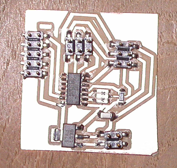
I modified the hello.servo.44 circuit design by adding TX and RX on two available pins on the ATtiny44. I used Eagle to develop the PCB. I had to work around the pin configuration for the LM2940 voltage regulator in Eagle as the component is not readily available in the libraries. I used the data sheet to adjust the pins used on a similar footprint item. This is reflected in the schematic.
Once the board was built, I attempted to load a sketch I had developed in the Arduino IDE. I decided use Arduino due to the simplicity of writing the PWM and communication routines using the Arduino servo and software serial libraries. However, on closer examination, the high-low tech add in for the Arduino IDE used to program the Attiny44 does not support the servo library. So to achieve my aim, I combined the C code for hello.servo.44.c with the serial communication routines I found in hello.bus.45.c in the networking and communication week.
This proved to be difficult initially as I had moved the output pin for PWM from that used in hello.servo.44. After detailed examination of the data sheet, I found I had unintentionally moved from a 16bit counter to an 8bit counter to control the PWM. As a work around I switched back to the output pin used on hello.servo.44 using a solder bridge. Once this was done, I worked through the communication routines to use a serial input to modify the PWM signal.
;
Finally I produced a short Processing sketch designed to generate a serial input control and display it on the screen.
The system operates, but needs further work to stabilise the initialisation routines as the system does not always function on being powered up.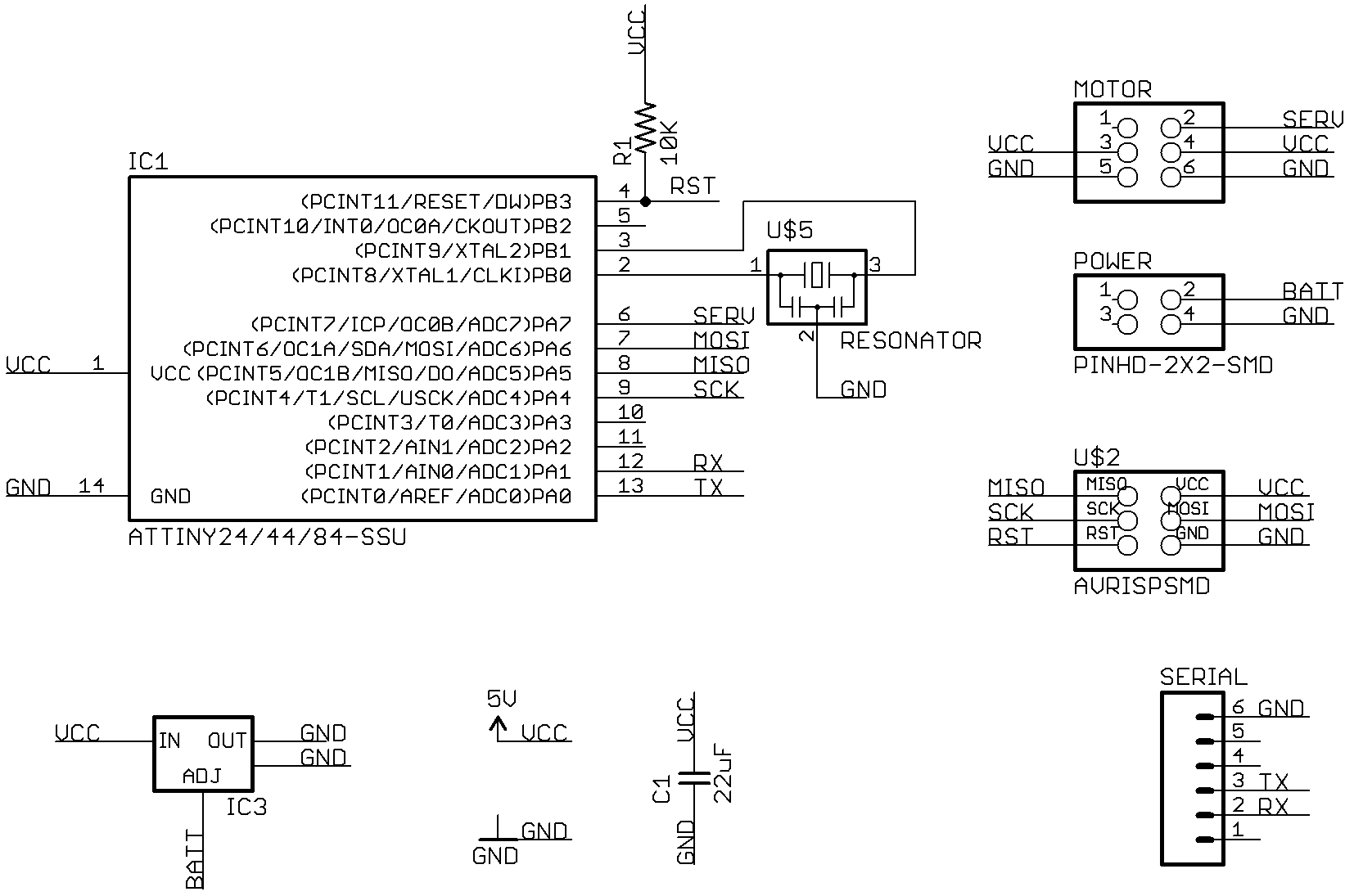