2013
.

For this assignment a servo is moved and the position is printed on the LCD screen. This has been done with a PSOC and my designed boards. PSOC designer 5.4 was used.
First, a new project was created selecting the correct target device.


After, in user modules, under PWM’s folder, a 16 BIT PWM is used. I will explain later here why I used a 16 bit PWM and not a 8 bit. This PWM will be used to move the servo

Then, I added the LCD under Msc Digital folder. In blue in the schematic, the 16 bit PWM can be seen

Now here comes the tricky part, selecting the proper clocks for the PWM. A typical analog radio control servo works at 50 Hz. This means that the period is 20ms. In order to move the servo, duty cycle from 1ms to 2ms have to be used. Only 5% of the duty cycle can be used.
Now suppose that I select a 8 bit PWM. This means I have 255 possible values. If 20ms is 255, then 1ms will be 13 and 2 ms 25. And so, I would only have 12 position resolution. This is very low. This is why I selected a 16 bit PWM.
If I divided the 24 Mhz internal clock of my boar by 50x2^16, if gives me 7.3. This would be my divider of my internal clock. I have to round it to 8 in order to keep 20ms with less or equal than 2^16 possibilities.
I select the PWM, in the upper left I select VC1 divider by 8 as can be seen in blue. In the parameters window I select VC1 as clock.
I select period 60000 (this is what 20 ms take) and starting pulse width 3000.

Then, I click on the LCD and select Port_2 witch is already mapped in the board to a LCD

After, with shift hold, I click on compare out in the PWM and then in any of the ports on the right without releasing shit in order to map the PWM output to a output port. I selected Port_0_7

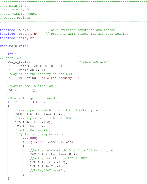
Then, the code has been done in C.


It was then built, and programed

Video demonstration


