Electronics Design
This week’s assignment was to redesign the helloEcho board and modify it by adding at least a button and an LED. I used EAGLE 6.4.0 light with fab and ng libraries to design the PCB.
The first thing I did was to draw the schematic. I used components from fab and ng libraries. I added a button with a pull down resistor at pin PB2 and an LED with a resistor at pin PA2. The additional components are shown inside the red rectangle in the final schematic shown below.
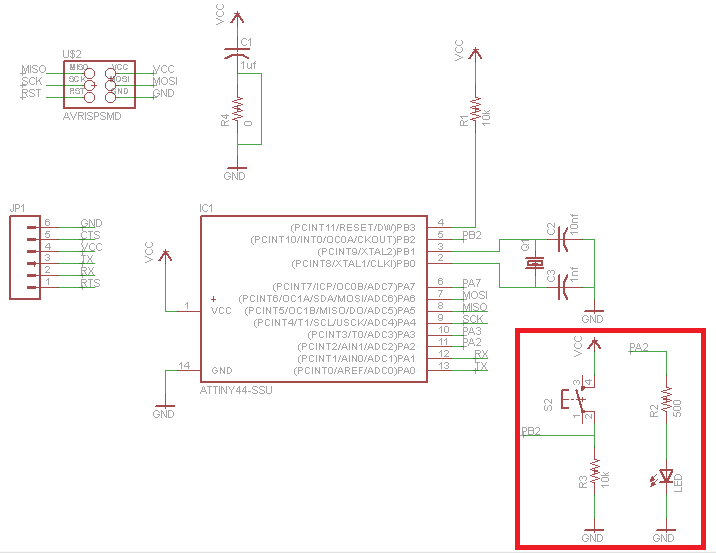
Final schematic
Then I designed the board from the schematic and exported a png file to be used with the fab module which is used to mill the traces with the Modela milling machine. I used a 0 ohm resistor at a point to avoid crossing over of PCB traces.
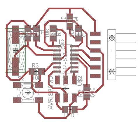
Final PCB Design
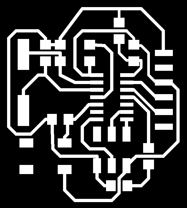
png file to be used by Fab module
Then, using the Modela MDX-20, the PCB was made, and the components soldered.
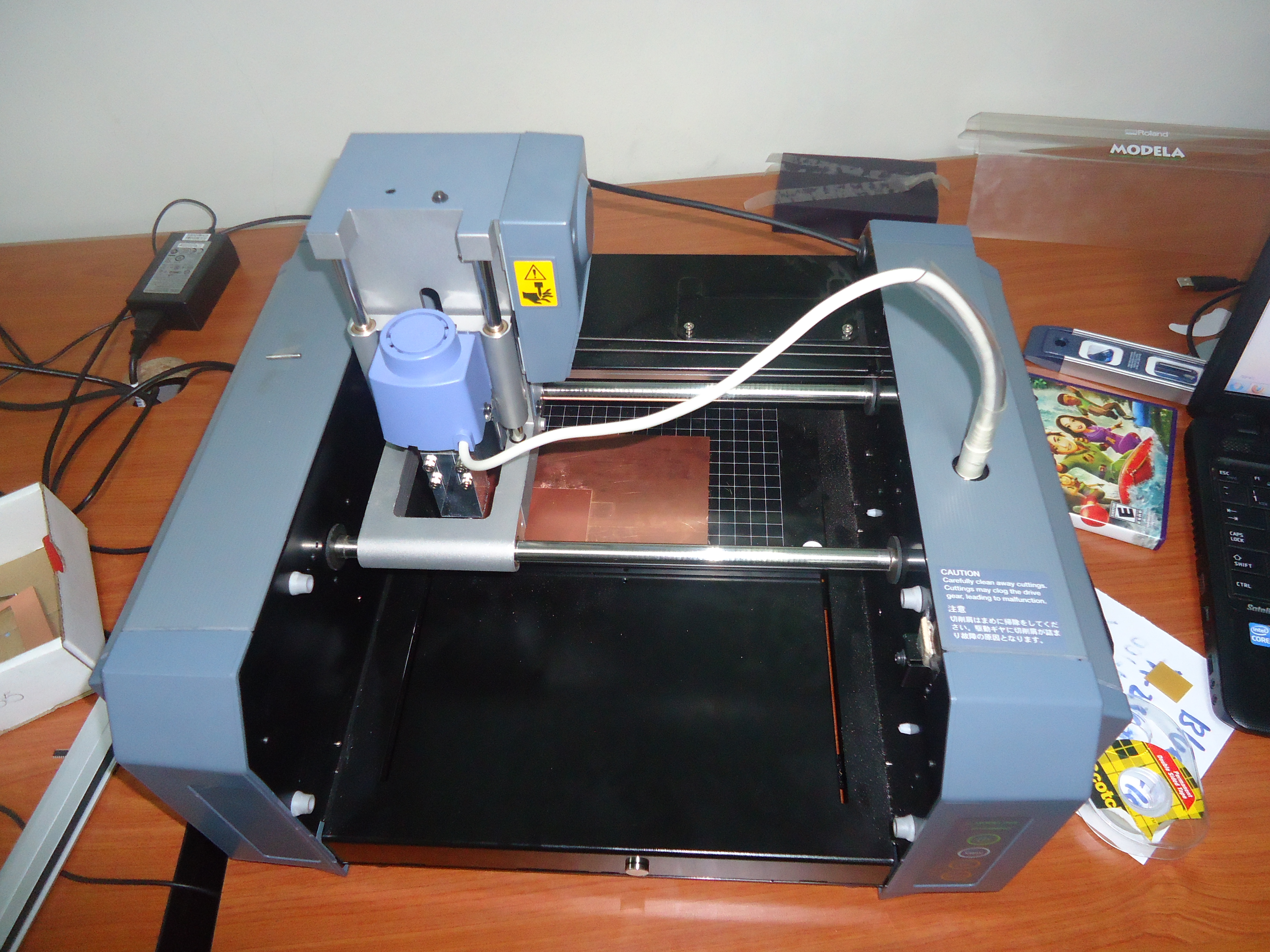
Milling with Modela MDX-20
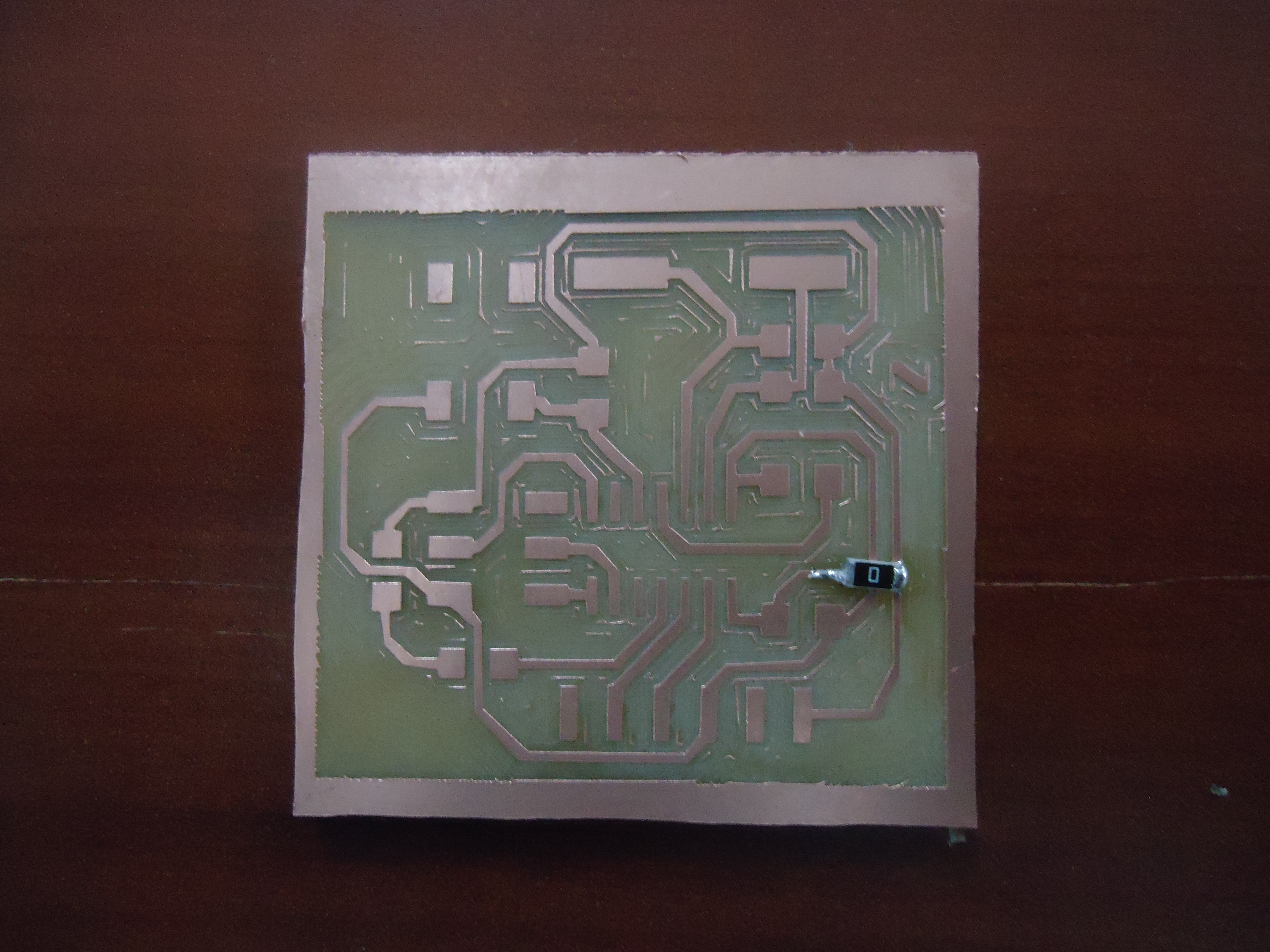
Final PCB with 0 ohm resistor soldered
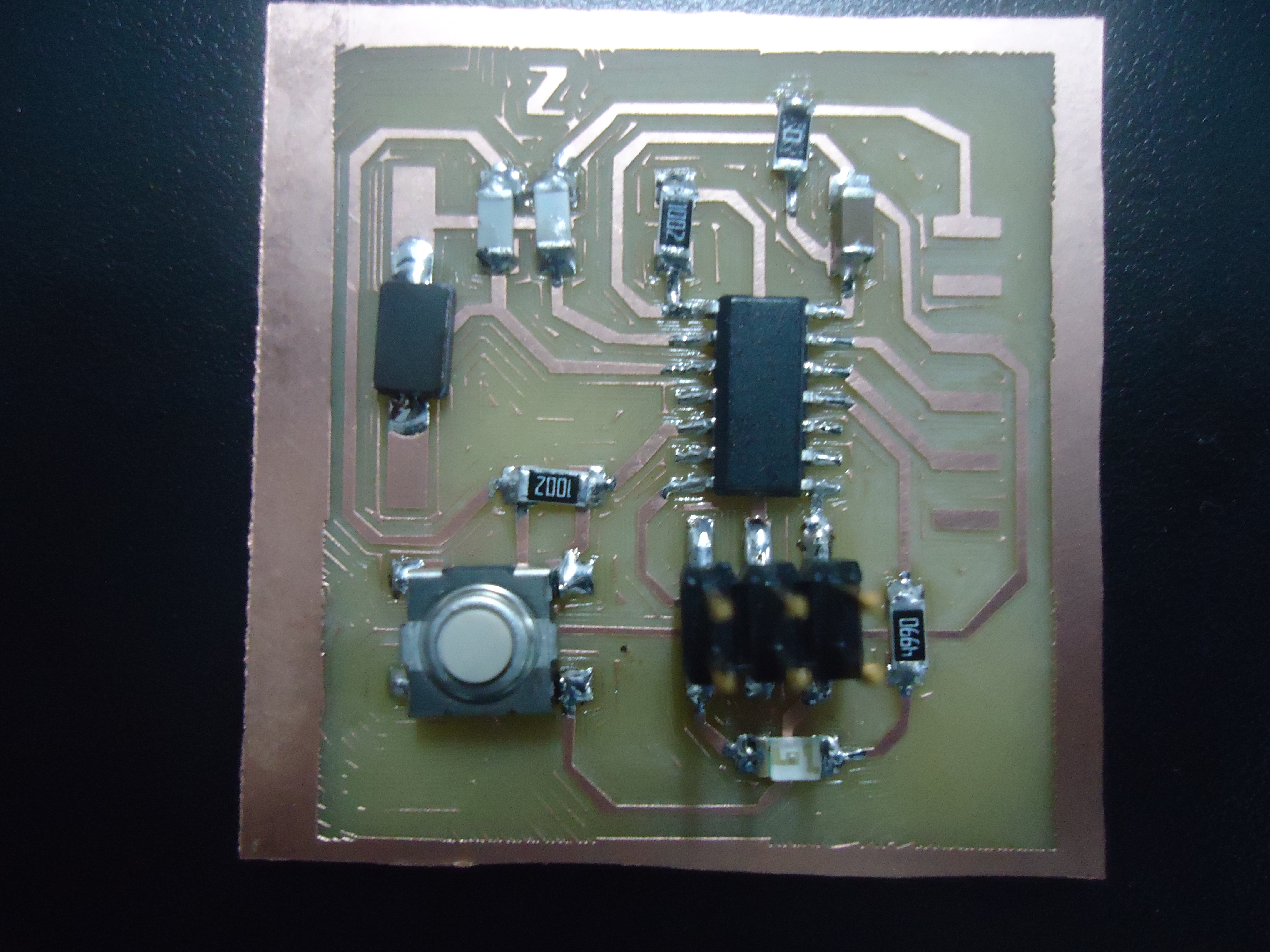
Board with components soldered