Electronics Production
For this week, we were given the task of making the FabISP in-circuit programmer as part of the electronics production class assignment. The task involved manufacturing a PCB and soldering components on the manufactured board. I hereby explain the steps I followed in doing the assignment.
Making the PCB
The board layout for FabISP in-circuit programmer is already available, so what was expected of me was to carve out the PCB traces. Unfortunately the Modela MDX-20 milling machine in our fab lab is out of order for some reason, so I had to resort to other means of making the PCB. The first option was to use a vinyl cutter, but this was unsuccessful due to the narrow width of the traces. There are some successful attempts to make PCBs using a vinyl cutter by previous Fab academy students, but I wasn’t patient enough to see it to the end. So I decided to make the PCB with chemicals. I used UV exposure and ferric-chloride etching to make the PCB. There are many good tutorials on the net on how to make PCBs using this method.
Trial using the Viny1 Cutter
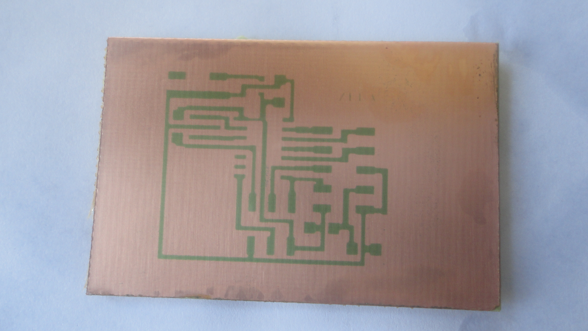
The first thing I did was to make the PCB traces wider, so that I don’t have to worry about traces breaking while the copper is etched. I modified David’s board design with eagle, making the traces as wide as possible.
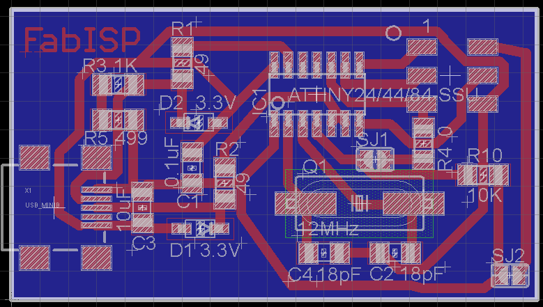
Modified PCB Traces
I was to use UV light exposure to transfer the traces to a board, so I had to use a transparent paper to print the traces, but instead I printed out the traces on a plain paper and used oil to make it transparent (I used what I had close by).
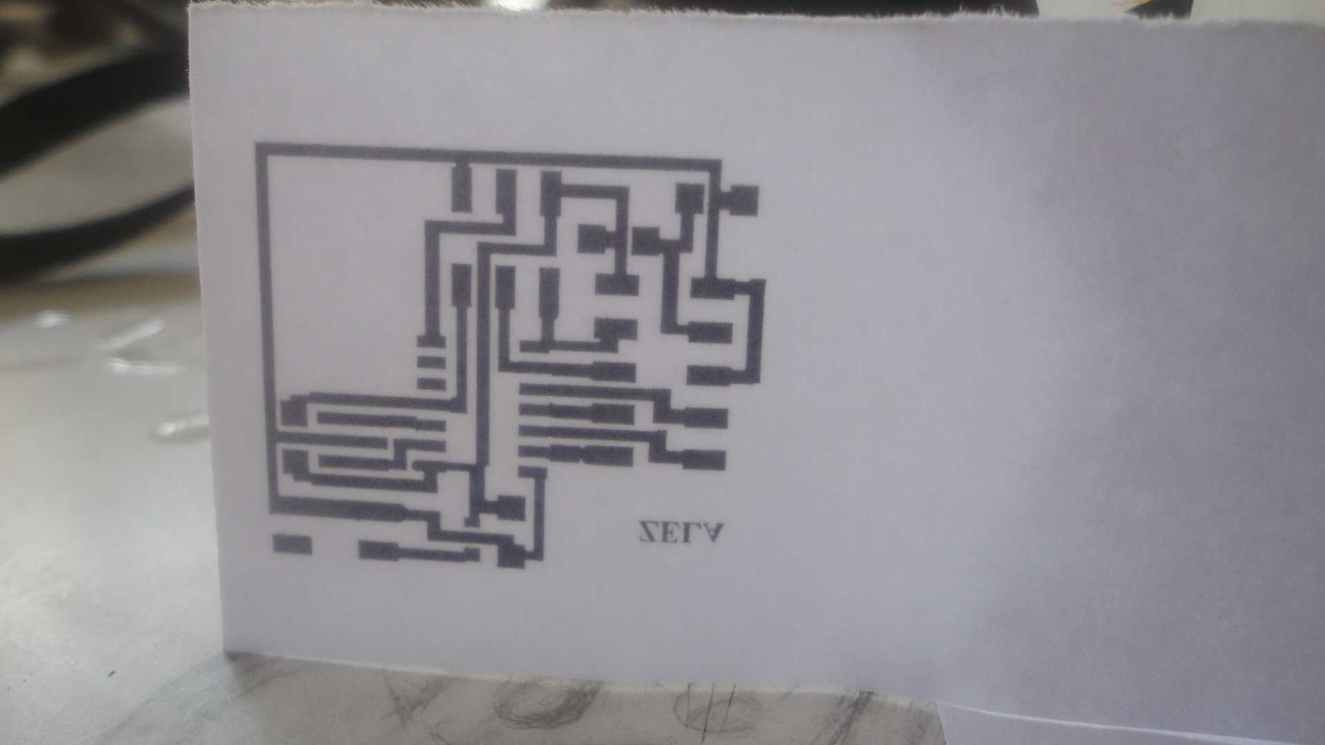
Printed Traces
The next step was to place the transparent paper with the traces on a photo-resist coated copper board and to expose the board to UV light for about five minutes. This way, part of the board where the copper is not needed is exposed to UV light.
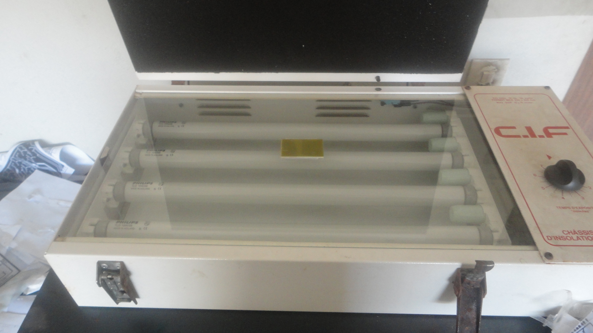
Copper Board inside UV light Box
The exposed board is then put into a dilute sodium hydroxide for development. The sodium hydroxide removes the photo-resist from the UV exposed copper, leaving the traces on the board.
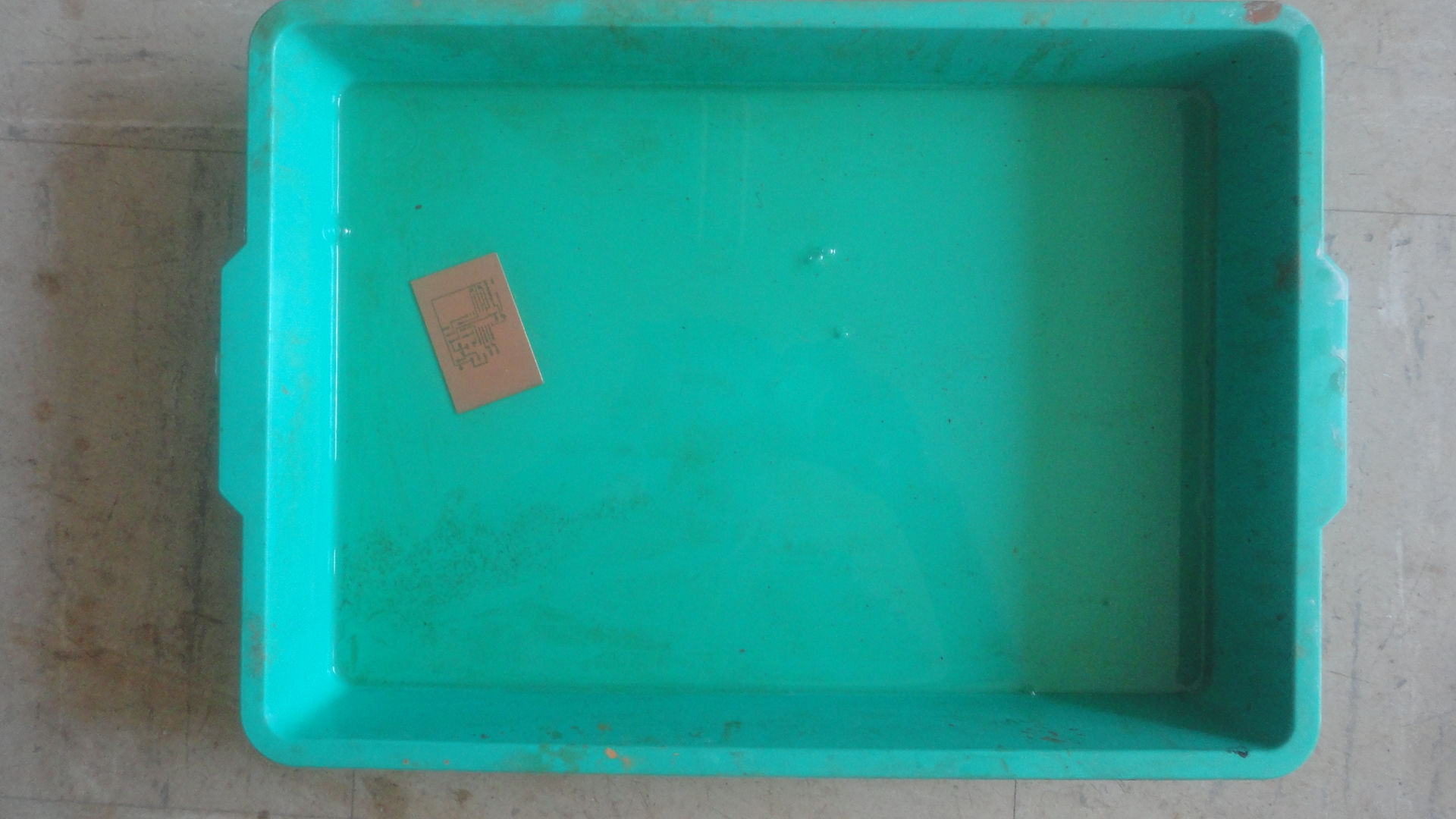
Board Inside Developer Developed Board
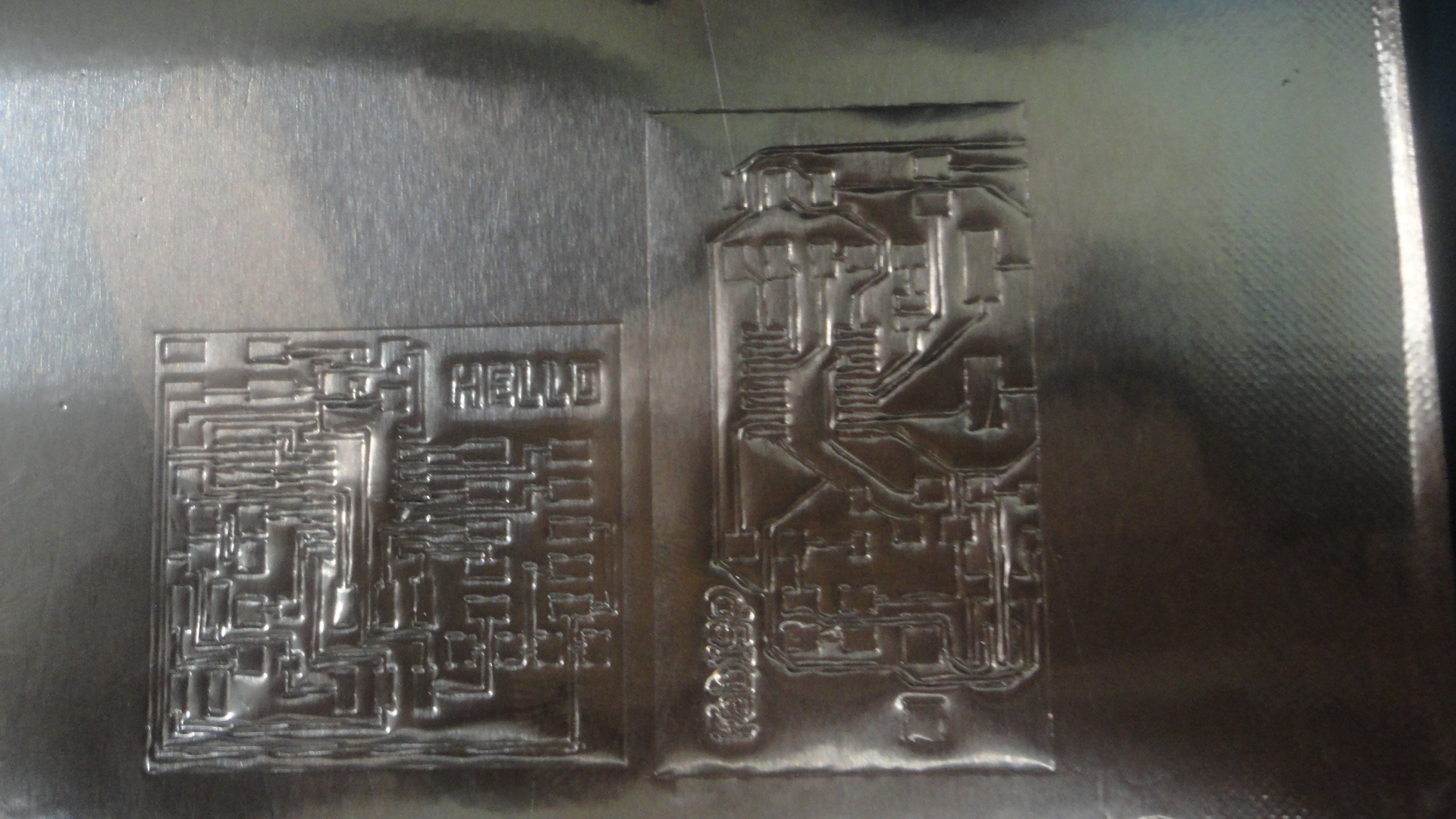
Finally the board is put into ferric chloride for etching. I used an old etching machine for this job. The etching removes the unwanted (UV exposed) copper from the board leaving the required traces. The final result was a nice board shown in the following picture.
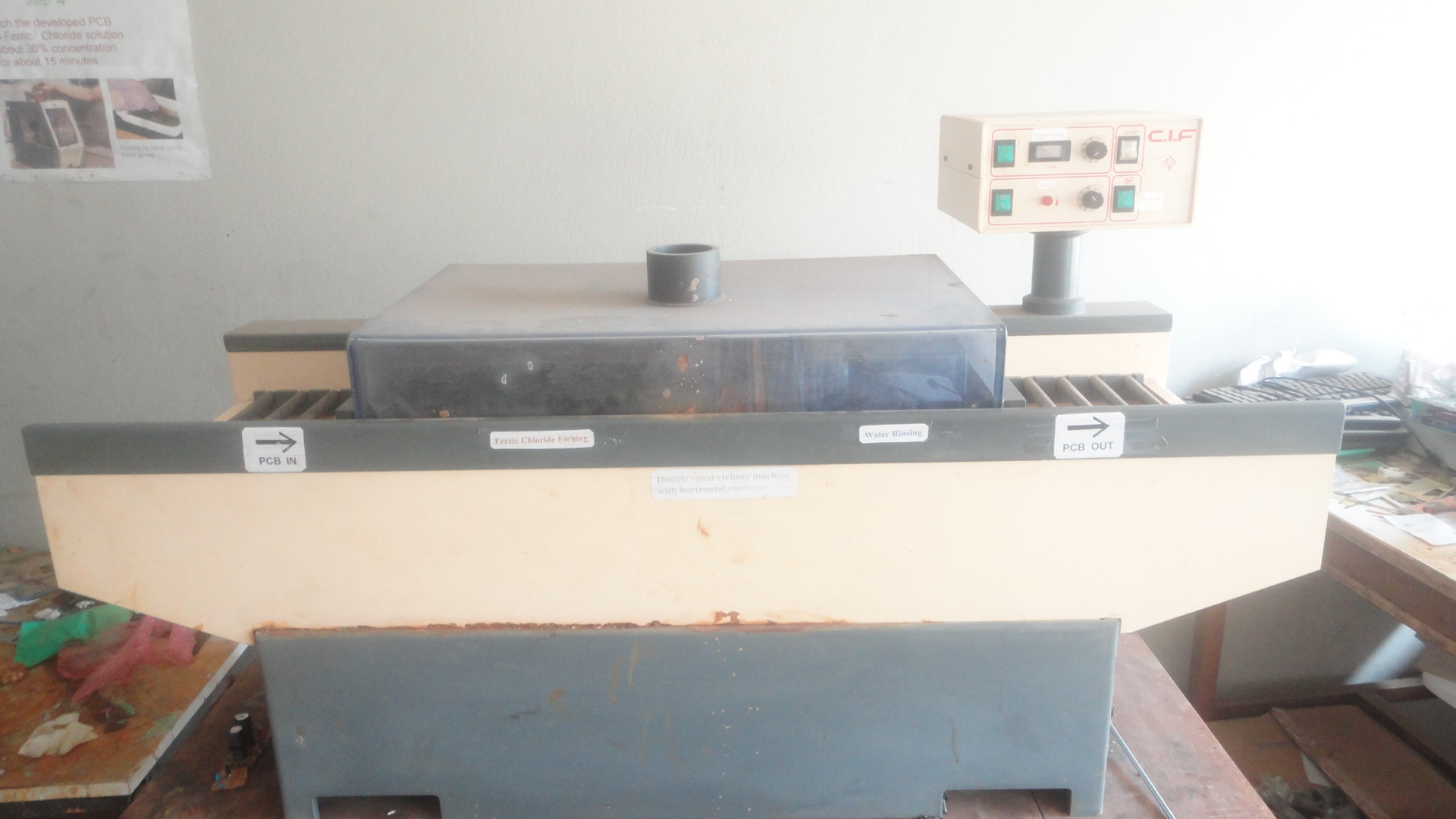
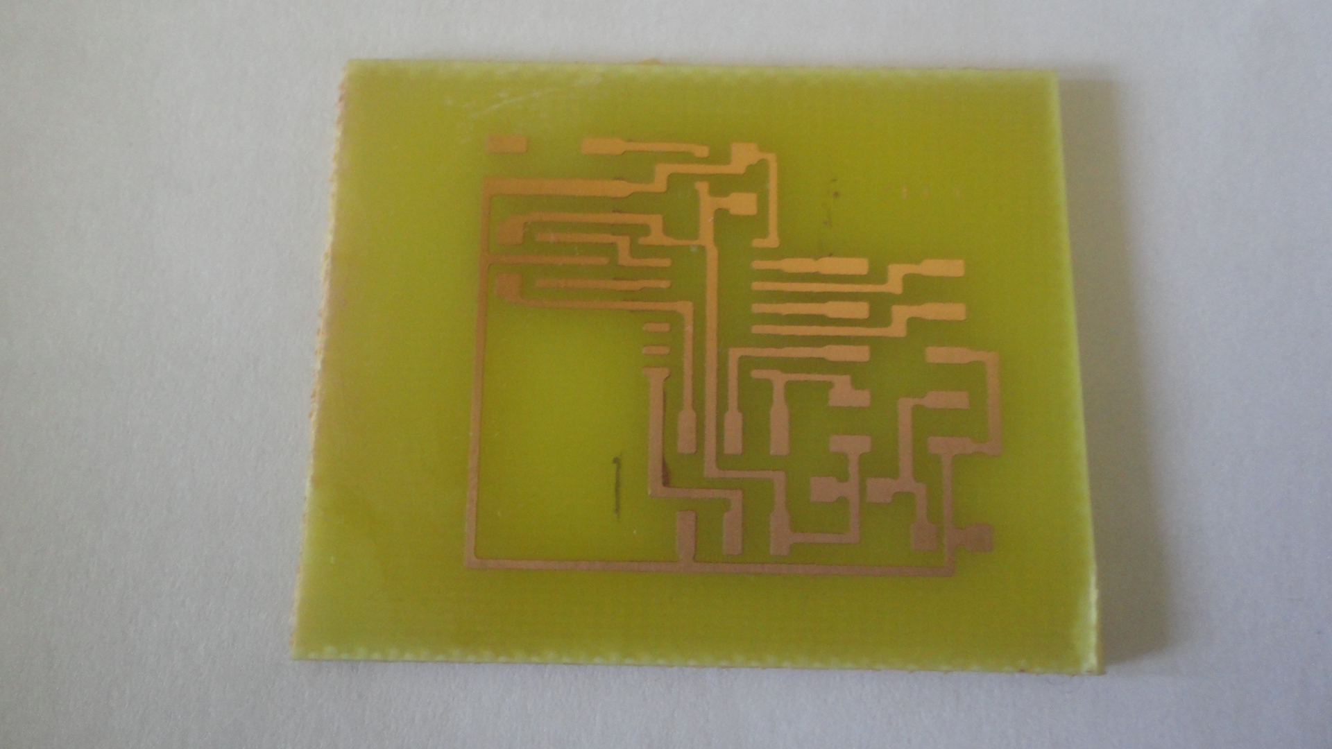
Etching Machine Final PCB
Soldering components
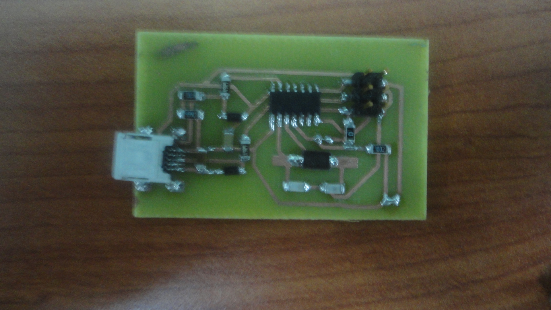
Final Board with Components Soldered