
Project Development - Final Project - HAB-SOM1
HAB-SOM1 (High Altitude Balloon - Sub Orbital Machine 1), is a modular and open-source platform for high altitude experiments and data gathering. The main parts of the system are the electronics for tracking, real-time data transmision and data recording, and the structure, designed to protect the electronics from the extreme conditions at high altitude and from impacts. Some other parts are also needed, like the deployment and recovery systems (balloon and parachute).
There is lot of documentation about high altitude balloon experiments, but my main goal with this project is to make most of the parts fabbable and opensource, and also experiment with this kind of systems for future projects.
So, during the FabAcademy, I did a lot of tests to try to find the best and cheaper parts, materials and software for the project, but I also wanted to try some new things and use all the fablab processes I can, so several design decisions are based on this. So, I'll try to explain why I choosed the main parts and processes.
Structure:
The structure has to keep the electronics safe from the environment at high altitude, with temperatures down to -50ºC, humidity, wind shocks etc. So first I was thinking on an aluminium structure with internal foam isolation. I intended to mill thin aluminium sheets on the milling machine and assemble them, and then make some isolation walls inside. You can see the first assignment for designs and renderings. The problem with this is that it's more difficult to make than using other materials, metal weights more, and it's more dangerous if it falls from 38Km high. So after trying some ideas, I choosed to use home isolation foam (thick and hard foam) to make the structure. This has some advantages, it's cheap, it's easy to machine, it's designed for isolation so the structure and the isolation are the same, and it's not very dangerous because... it's foam. After some tests (see parachute test), I decided the final design of the outer structure, using a slot design machined on the cnc mill, covered with material from a thermal blanket for added isolation. Then the rest of the structure was designed arround the electronics and supports needed, like the parachute supports and spreader, and the supports for electronics and antennas.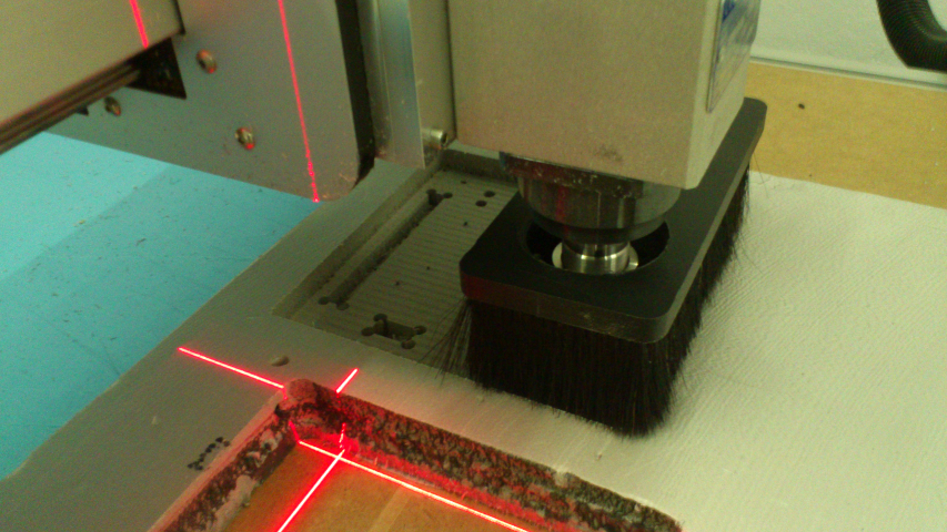
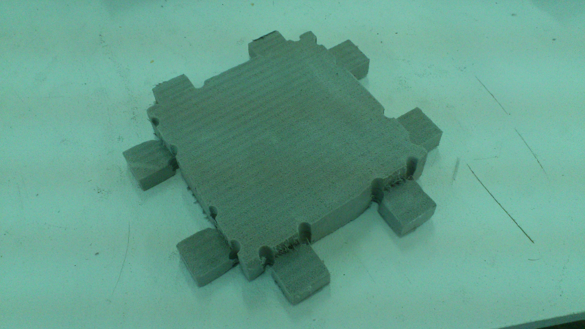
Here you can see the assembly of the foam parts:
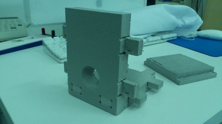
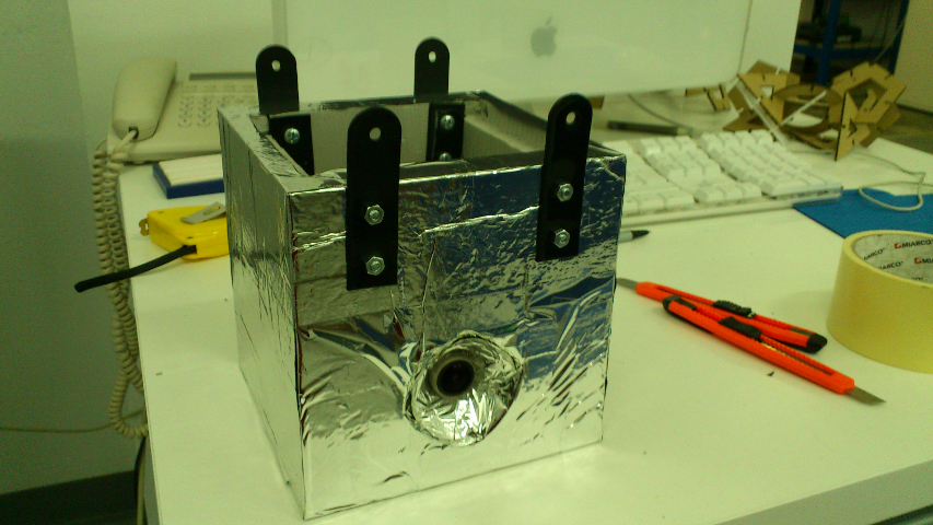
The complete assebled enclosure:
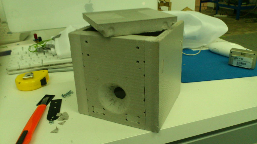
The enclosure after covering it with the isolation material, and adding the line supports:
And for eye-candy, the project logo on vinyl:
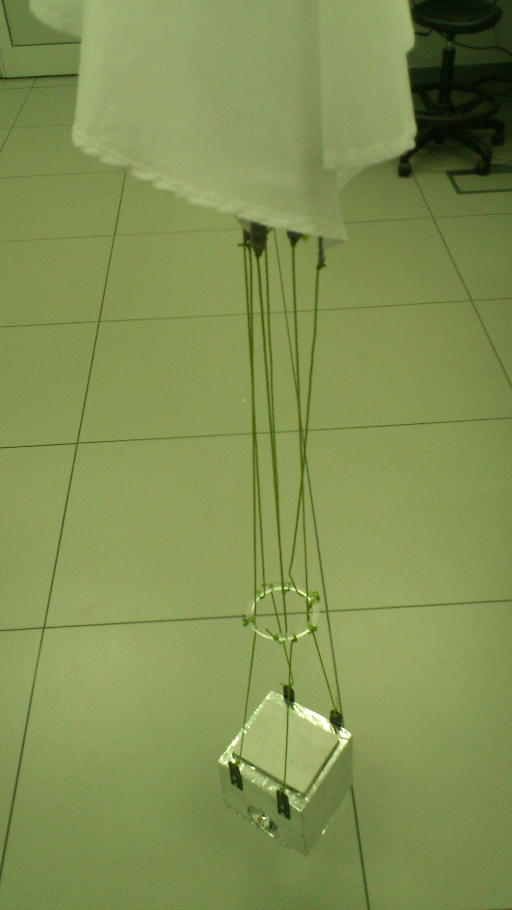
And the completed "vehicle" with attached lines, parachute spreader and parachute:
Testing of the system:
Electronics:
The electronics for this project had to be cheap, low power and easy to source, but as I said, I also wanted to try new things. I worked with AVR microcontrollers for years, but lately I started to experiment with MSP430 microcontrollers, so this project will be a nice time to try them. MSP430 microcontrolers are really nice for this project as they are low-power, cheap, easy to source, and powerful. I decided to go with a value line MSP430g2553, a 16bit ultra-low power micro with 16K of FLASH and 512bytes of RAM, with two 16 bit timers, UART, I2C, SPI, IRDA, 8 ADC, etc.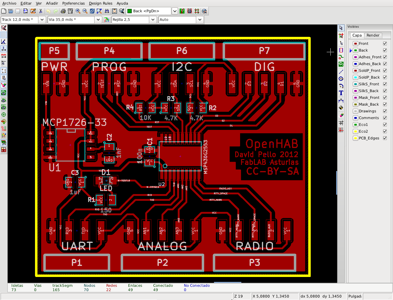
For programming, I'm using the GNU GCC and related utilities for MSP430, and on the hardware side, using the USB programmer and debugger from the MSP430 Launchpad, a 4.30$ development platform from texas instruments. Then, for the rest of the electronics, all the decisions were made based on experience, documentation and availability. The radio system is based on a radiometrix NTX2 UHF module. This radio has been tested by radio amateurs for traking, APRS, etc, and performs great. The power system is really simple, using the simplest li-ion battery charger IC I could find. Li-ion batteries were chosen because they are lighter and cheaper than other alternatives, and you can buy them from distributors already on the inventory (hobbyking). I decided to go with a 2cell (7.4V) 2200mAh battery, that was tested for more than 7 hours of continuous radio and subsystems operation. The communications back-up system it's an arduino GPRS modem shield, cheap and easy to adapt to work with my electronics, and the sensors are the ones that I found easier to use, realiable, and with clear documentation and examples on the internet.
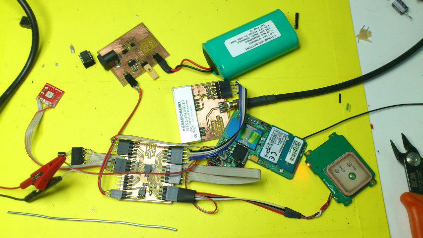
In the above picture, you can see the main board, the power board (battery charger and regulation), the radio board, the GPS and GPRS modules, and two sensors, the LM35 (external temperature) and the BMP085 (internal temperature and barometric pressure).
Communications and Tracking:
When you send a balloon up 30Km or more, you need a tracking system if you want to recover it. The traking system of the HAB-SOM1 has a GPS-based positioning system with real-time data broadcasting by radio, and a backup system using the cellular network with a GPRS modem. The system gets data from a GPS module, parses it, and sends position and sensor data through the UHF (434MHz) radio using the RTTY protocol. RTTY (Radio Teletype) is a very simple protocol used by radio amateurs for long distance data transmissions, it's simplicity (it's a binary systen using two adjacent frequencies for the two symbols, "mark" and "space" that form the "bytes" of the data, makes it really good for computer decoding in low signal/high noise conditions. The HAB-SOM1 is using 7 bit (ASCII), 50 bauds RTTY with a space of 350Hz between symbols. All this is very standard for RTTY. For receiving the data, an amateur radio is used, feeding the audio signal to a computer that decodes the data using the FLDigi open source software and saves it to a file, that can be parsed in realtime in order to extract the telemetry (GPS and sensor data). This way you can track the balloon in order to find where it will land. As the radio link can be lost, specially when landed if it's behind a hill or a forest, a backup system has been designed that sends a SMS with the GPS data to a designated phone each 15 minutes. If you lost the radio link, you can wait and get a SMS with its position. And at last, there is a light and sound beacon, activated when the device lands (guessing from gps altitude) or when the main battery runs out (it has it's own backup battery). This way you can find the probe if it lands in a difficult place (like a forest) or the GPS data is innacurate.
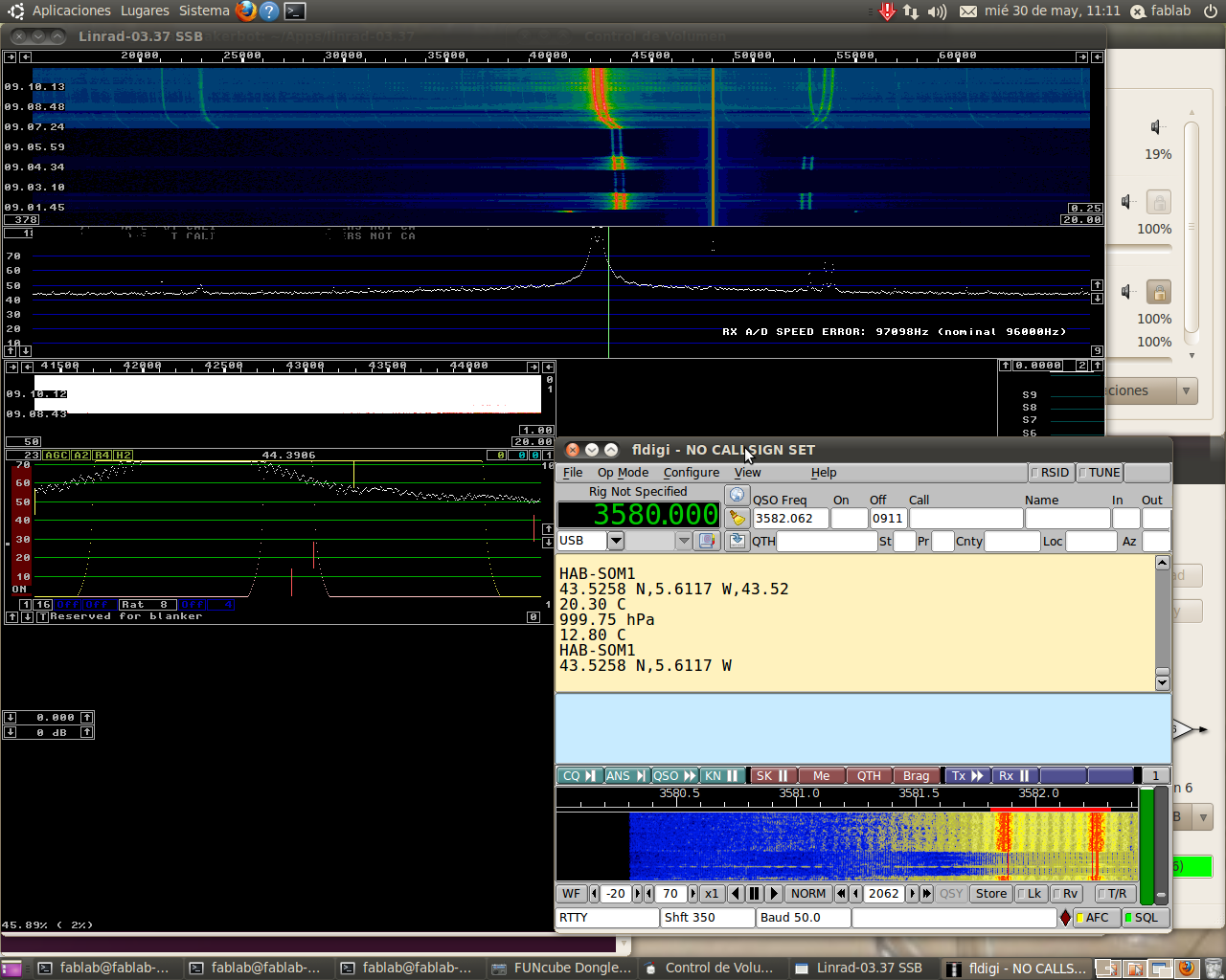
Here you can see the data received using a funcube dongle SDR radio, linrad SDR software, and fldigi for decoding the RTTY (The sensors are not calibrated for the final 3.3V supply, as the development platform runs on 3.6V):
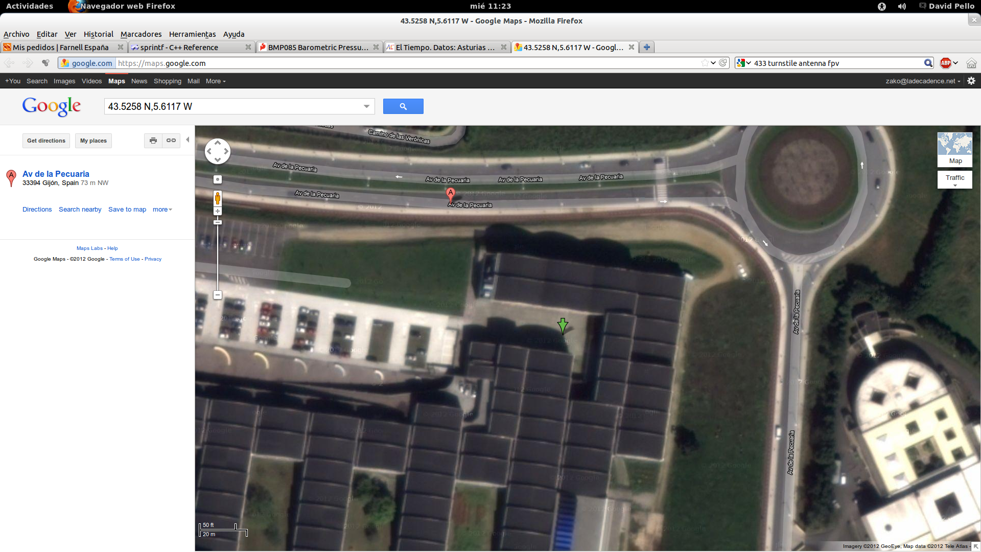
The GPS data is perfect, as seen in google maps with the coordinates provided in the transmission:
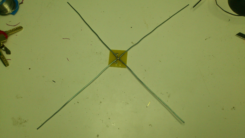
The main antenna is for the 434MHz radio link, it's an antenna designed by amateurs for long distance FPV (first person view) RC flight. It's omnidirectional, spherical radiation pattern, and dual polarized, so reception does not fade depending on the attitude of the probe. I designed a small PCB where you can solder #12 AWG solid wire, two pieces on 90º angle, with 5.85" one side and 6.75" the other, then feed one of the pieces with the signal wire from the coax, and the other with the shield:
Payload:
The payload for the first flight will be a group of sensors to gather data from the environment for future missions. The system will have an external temperature sensor (lm35), an internal temperature and barometric pressure sensor (BMP085), and accelerometers. The probe will be equiped also with a videocamera (GoPro) to record the flight. As some of the data can be lost on the radio link (as the probe moves with the winds you can loose the signal from time to time), the data will be recorded on an 256K EEPROM memory (I2C). The data packets are about 80bytes with a rate of 1 packet each 10 seconds, so with 256K, the system can record data for about 5 hours.The complete system ready for transmission testing:

Testing:
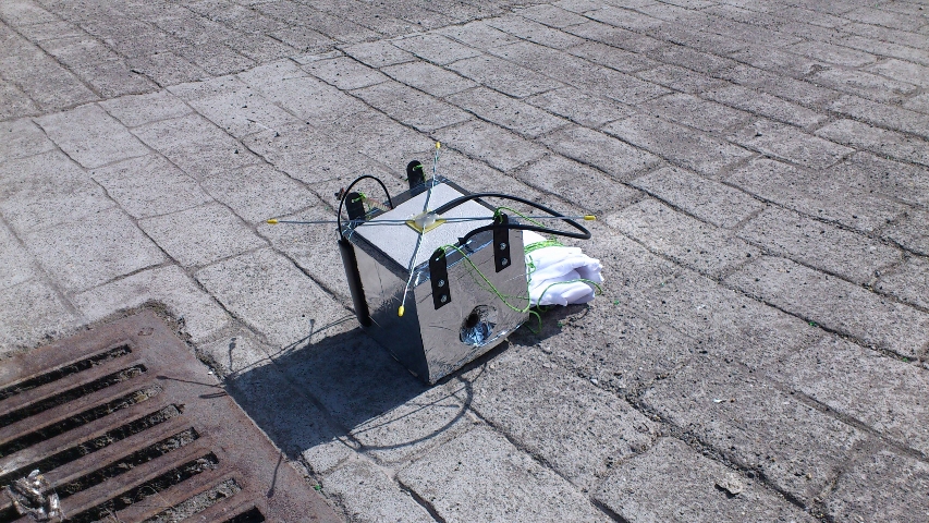
Final parachute test with all the electronics inside and antennas attached (final weight):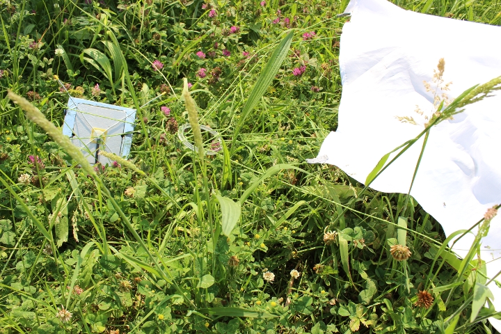
Parachute and video recording test:
Project Files:
CAD:Hardware:
Firmware:
As a bonus, I have a side final project: Surprise!