John O'Keefe
Week 16 - Machine Design
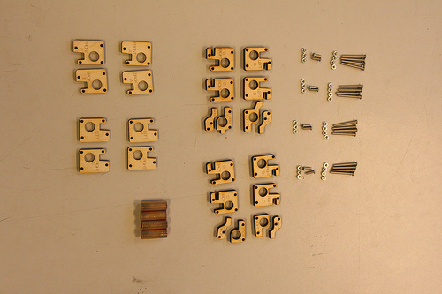
Ultimaker XY Sliding Block Assembly
 We ran into some issues with the alignment (ease of movement) of the extruder on the XY rods. We didn't have the specified bushings (we were using 2 smaller ones per assembly - 1 in each end), and thought this might be the problem.
Modified Sliding Blocks
 We ordered linear bearings as replacements for our questionable 2 bushing method. The sliding blocks now needed to be modified to accomodate the wider, longer bearings. We decided to model and print solid blocks both for better precision and to limit the number of parts in each assembly.
Prototyping
 We did a version with laser-cut pieces but the laser was misaligned and threw the assemblies off considerably. Making the holes just tight enough to fit, then hold the bearings in place, took some doing but we finally worked it out.
Final 3D Printed Sliding Blocks
 Outside pieces of sliding block assembly are the same - mirrored - with variations at the centers (little horns that engage kill switches when sliding blocks and extruder have gone too far). Basically, the 2 outside pieces of one side were extruded and combined, then mirrored. A longer sliding block meant longer screws but nuts were no longer needed as screws basically tapped the plastic holes.
XY Assembly
 Cross bars (that the extruder moves on) are held in place by a lowered arm which is pinned tight by a piece of laser cut plywood. Extruder alignment is off so for the time-being makes sliding block movement on rods jumpy. We need to take another look at the extruder.
Sliding Block On Rod and Drive Belt Held In Place
 Once sliding blocks are on rod, the little arm is lowered onto the drive belts holding them in place. Stepper motors drive sliding blocks along X and Y rods which in turn moves the extruder.