Computer Controlled Machining.
As part of my final project, developing the second component, the structure of the artificial environment q. Inspired by the project Fluoralife You can see the video
Summary of this Project
Fluoralife is a customizable, growing and interactive garden of Kinetic objects. The Miniflo's (or mini-flowers) are designed by the user who can select from a "candy shop" of parts. The user can also select a Moflo (or mother flower) to plug their creation into. Depending on which Moflo they choose, their Miniflo will respond to different actions of Light, Sound or Movement. The result is a garden that changes over time, educates students about inputs and outputs, reacts and emerges behavior and aims to make workspaces more playful. The garden as an open concept can be applied to many workspace scenarios and by extension, used as indicators for various workspace interactions.
Progress Description:
Concept
Nature is determined by a number of simple events and the sequence of events generated by the complexity and chaos, difficult to determine, intend to generate a nature que pueda information and feed back in response from an event generator, There are two components to this
The Pandora's Box

Pandora is the first component in each of their lateral sides have a flower 4 petals with numbering of 1 to 4, depending on the combination defined by the user and the return of another variable This will open, is like a simple game, This box can generate totals from 4 to 16. Still not solve the total central mechanism ewhich end up in the course of the other assignments.
El Jardín

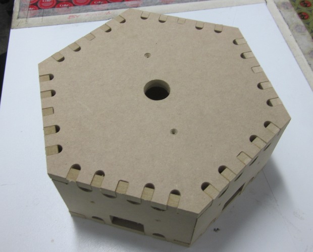
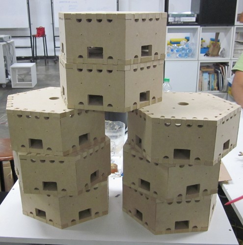
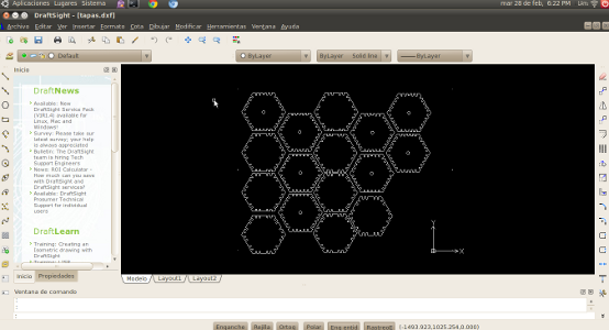
The Garden is the second component, is where are to be received inputs generated by the box Pandora, each unit has a hexagonal shape, each side has one input and output for connecting sensors, so you can join each of the hexagons in any order, and unite from all sides of each hexagon, each joint causes a different event in both input and output. The set of these units call it the garden, these units behave as flowers, where each output is the input of the next unit.
Show a graphic summary of the idea

La Producción
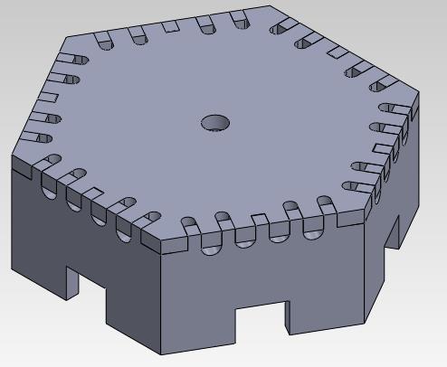
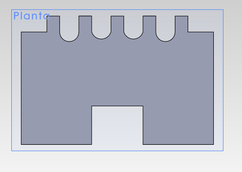
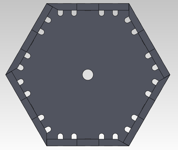
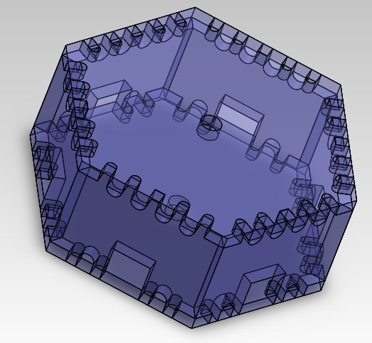
For this assignment I build 8 hexagonal cells joined by press-fit, At first consideration is to the material, MDF use which is not uniform throughout its length, therefore it works with an average, in my case 12.5mm, determined this thickness, the design is reduced by 0.1 mm being the final thickness of 12.4mm. Always work in SolidWorks, although I am slowly trying new processes, ahere are the views and the final result:
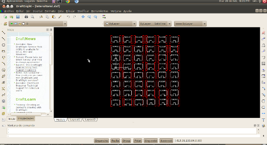
Back to 3D modeling in Solidworks, DXF file export each, DXF for working this time I decided to use something new, use DraftSight Its environment is very friendly, is opensource, and can open files dwg, dxf, and that is where do the ordering of my pieces, the image on the left side are the junctions, with an inclination of 60° and takes place in another layer (red)
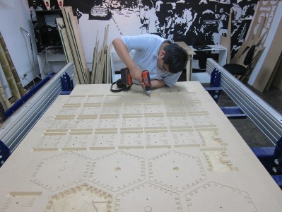
For Shopbot used two types of mills, one for the 60 ° and the other for the cuts of 90 °, These cuts of 90 ° made with 3mm diameter mill, because in preliminary tests of 6mm kept a good finish. They can also observe tools use generatesl


After selection of strawberries and tools ebegin the process within the programs of the shopbot, the machine has two settings, a machine control (sis activated with the key K) and drawing Shopbot Part Works 3D

To cut there are two important steps, the first to place the screws and the second is the cut of our design. For the first step was first carried out to determine the dimensions of the material, is measured across and the material thickness vernier, then the axes (X,Y,Z), the axis (X,Y) We assume that this default, ethe Z axis has two calibrations one for the screws and one for the court This is because the material collapses when it is fixed because of the screws. After calibration screws are positioned, if small parts should place them two screws in the piece as the paths are useless for these dimensions. then select the menu "DrillPath" is defined when the drill has to penetrate (2mm) and runs. For the implementation there are two steps, file is loaded, it starts ("button start") spress the green button on the remote and then press "accept". Then placed the screws in the marked area.
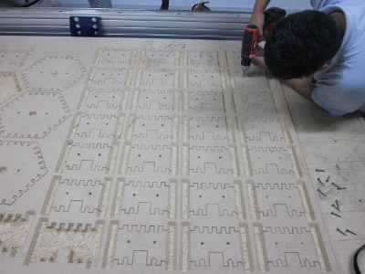
After the screws are re-calibrating the Z axis, parts are positioned, and defines the type of travel of the mills, in my case was a external route.for my side pieces, first make a cut with the mill 60 °, change of strawberry and proceed to cut with the mill 90 °. which resulted in the end the following: