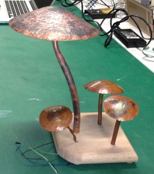
For my final project I built a color changing RGB led lamp. The color of the led is controlled by three capacitive touch sensors. All of the sensors and the led are controlled by a "Fabduino" which is a n Arduino clone that I fabricated. I will break the build down into two sections, the structure and the electronics.
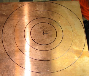
I wanted the structure of the lamp to have a somewhat organic look. I decided to make the lamp look like a large mushroom and the three sensors like smaller mushrooms growing around the base. To form the large mushroom cap I started with a sheet of .032" thick annealed copper sheet. I marked the center of the sheet and drew an eight inch diameter circle on it with a compass. I then drew three more concentric circles each about 1" smaller than the last. These smaller circles are reference lines to help during the raising process.
Using a pair of tin snips, I cut along the outside line to make an eight inch disc. Due to the cutting method I used there were several burrs around the edge of the disc. I clamped the disc into a bench vise and used a mill file to smooth the edge all the way around the disc.
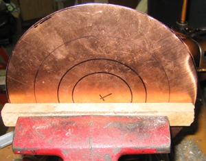
With the burrs removed and the edge smooth I was ready to start the raising process. Raising is a method of metal working in which a piece of sheet metal is formed by repeatedly hammering it over a stake or other form. For my stake I used an old railroad spike that I had cleaned and polished the top of. I put the spike into my bench vise and secured it in place.
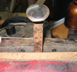
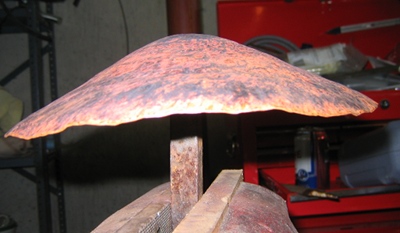
I lined up the center of my disc with the top of the spike and began to hammer it while slowly rotating the disc as I went. The idea is to slowly work from the center to the outside edge in a tight spiral pattern. I use the reference lines to help keep the pattern even but don't worry to much about it being perfect. Additional passes will help fix any funky areas. Keeping a consistent pattern without hammering the same place twice is key to a good shape. After each round of hammering the piece becomes work hardened and needs to be annealed to soften the copper and keep it from cracking. This is what my piece looked like after the first round.
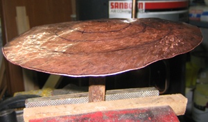
Annealing is a process of heating and cooling that alters the metals structure and makes it more ductile. To anneal my piece I heated it with an acetylene torch until it was glowing orange. You want to keep the torch moving on the piece to make sure it is heated evenly. Once you reach a consistent orange glow you can remove the heat and let the piece cool or you can quench it in water. For the sake of time I put my piece into a five gallon bucket of water. The annealing process although simple is dangerous. Be sure you wear proper protective gear and work in a well ventilated area. Once the piece is annealed its back to the stake for another round of hammering. Hammer, anneal, hammer,anneal again. Continue until you get the shape you want. For my large mushroom it took four to five cycles, and three to four hours from start to finish. The finished cap looked like this.
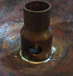
After raising the large cap I repeated the same process three more times using 3 1/2" to 4" discs to make the caps for my sensors. With the caps done it was on to the stems. For my large cap I used 1/2" m type copper pipe to form the stem. All I did was anneal the tube so it would be easy to bend and bent a nice curve in it by hand. For the smaller mushrooms I used 1/4" tube so it would look proportional. To attach the stems to the caps I cleaned a small area on the underside of the cap with fine sand paper. I applied paste flux to the clean spot, heated it with the torch and melted a pool of solder onto it. Then I placed the stem on the solder pool and reflowed the solder while holding the stem in place. On the large mushroom I didn't solder the stem directly to the cap. Instead I soldered a 3/4" X 1/2" reducer coupling that I predrilled 2 holes into the side of to the cap. The stem slides into the small side of the reducer allowing me to split the two parts for wiring.
The last part of the structure was the base. Initially I just kept it simple and took a piece of 3/4" oak that I had kicking around and drilled some holes in it that the stems fit into. Eventually I want to use a piece of a log or driftwood to give it a more natural / organic look.
For the electronics portion of the build I knew I wanted my lamp to be Arduino based because I am comfortable with the IDE. I also wanted it to be easy to change, modify and reprogram. I had built a "fabduino" earlier in the course and decided to use that as a start point. I knew I could write a sketch to control an RGB easy enough so the challenge was the capacitive touch sensors. Poking around on the web I quickly found the capsense page of the Arduino Playground. This gave me lots of good information, links to videos and the capsense library for Arduino. I started off with Paul Badgers example code from the capsense page. It is set up with three sensors running on four pins from the Arduino. To get started I modified the pinouts in the code to work with the pins I had available on the "fabduino". I wired up a breadboard with a single sensor. I connected the sensor using a 10 Megohm resistor between the send and receive pins and a .01uf capacitor between the receive pin and ground. This made for a very sensitive touch pad. Looking at the data on the serial monitor I could see It was picking up my hand about three to four inches above the sensor. A quick change to a 1 Megohm resistor reduced the sensitivity so that I actually needed to make contact with the sensor. With my sensor working I added an if / else statement to the code and a white led to the breadboard. I increased the delay to make it so I could read the data coming in from the sensor and adjust the threshold. The numbers coming in from the sensor were quite large and I found that a threshold value of 1500 seemed to work pretty well. Here is my code
#include/* * CapitiveSense Library Demo Sketch * Paul Badger 2008 * Uses a high value resistor e.g. 10M between send pin and receive pin * Resistor effects sensitivity, experiment with values, 50K - 50M. Larger resistor values yield larger sensor values. * Receive pin is the sensor pin - try different amounts of foil/metal on this pin */ //CapSense cs_4_2 = CapSense(4,2); // 10M resistor between pins 4 & 2, pin 2 is sensor pin, add a wire and or foil if desire //CapSense cs_4_6 = CapSense(4,6); // 10M resistor between pins 4 & 6, pin 6 is sensor pin, add a wire and or foil CapSense cs_7_8 = CapSense(7,8); // 10M resistor between pins 4 & 8, pin 8 is sensor pin, add a wire and or foil int ledpin=9; int ledpin2=10; int brightness=5; void setup() { pinMode(ledpin,OUTPUT); pinMode(ledpin2,OUTPUT); //cs_7_8.set_CS_AutocaL_Millis(); // turn off autocalibrate on channel 1 - just as an example Serial.begin(9600); } void loop() { long start = millis(); long total1 = cs_7_8.capSense(30); // long total2 = cs_4_6.capSense(30); //long total3 = cs_7_8.capSense(30); Serial.print(millis() - start); // check on performance in milliseconds Serial.print("\t"); // tab character for debug windown spacing Serial.print(total1); // print sensor output 1 Serial.print("\t"); // Serial.print(total2); // print sensor output 2 Serial.print("\t"); // Serial.println(total3); // print sensor output 3 if (total1>1500) { brightness=brightness+5; analogWrite(ledpin,brightness); analogWrite(ledpin2,brightness); Serial.print("TOUCHED!"); // print sensor output 1 Serial.print("\n"); Serial.print(brightness); // print sensor output 1 Serial.print("\n"); if (brightness>240){ brightness=0; } } else{ Serial.print("not touched"); // print sensor output 1 Serial.print("\n"); } delay(5); // arbitrary delay to limit data to serial port }
With a basic loop working I started noticing that sometimes the sensor was not picking up my touches and the data coming in was varying quite a bit. To try to improve this I changed the capacitor from a .01uf to a .001uf. This reduced the size of the numbers being reported in the serial monitor and improved their consistency quite drastically. The next step was to go to the full 3 sensor set up and wire up the RGB. I changed my code to add the 2 additional sensors and adjust the threshold value. I also added 2 more outputs so that I would have one for red, one for green and one for blue. I also made it so that each touch would increment the PWM value by 15 to limit the number of touches to cycle through each color. I did have a few issues with setting up the RGB led. For some reason I blew the red chip a couple of times. I checked the value of my current limiting resistor. I had set it up to limit the current to 20ma. The max current for the red on the data sheet was 30ma so it should have worked. However, should have and do are two different things. After blowing a second led I increased my resistor value to limit the current to 15ma. That took care of that problem. The other problem that I had was my Fabduino was a little flakey some times. Some times it would run perfectly and some times it would freeze up or act erratic. After doing a little more digging around on the web I came to believe it was a grounding issue. I wired an external ground to my breadboard and attached it to a grounded wall outlet. This seemed to help but the unit would still freeze up some times. It seemed very dependent on where I set it up. At home it was perfect, at the lab it was sketchy. I don't know if this is because my outlets are grounded better than the labs or if it is something else all together. So although I feel like my project worked it still needs some fine tuning. I need to design a board in Eagle to connect up my sensors, my led and external power so I can lose the breadboard. I also need to figure out the grounding issue. I'm hoping some of it is due to the breadboards typically poor connections. So here is my final working code and a video clip of the lamp cycling through the colors.
#include/* * CapitiveSense Library Demo Sketch * Paul Badger 2008 * Modified by Ted McAuliffe 2012 * Uses a high value resistor e.g. 10M between send pin and receive pin * Resistor effects sensitivity, experiment with values, 50K - 50M. Larger resistor values yield larger sensor values. * Receive pin is the sensor pin - try different amounts of foil/metal on this pin */ CapSense cs_7_12 = CapSense(7,12); // 10M resistor between pins 7 & 12, pin 12 is sensor pin, add a wire and or foil if desire CapSense cs_1_3 = CapSense(A1,A3); // 10M resistor between pins 1 & 3, pin 3 is sensor pin, add a wire and or foil CapSense cs_7_8 = CapSense(7,8); // 10M resistor between pins 7 & 8, pin 8 is sensor pin, add a wire and or foil int redpin=9; int greenpin=10; int bluepin=5; int brightnessred=15; int brightnessgreen=15; int brightnessblue=15; void setup() { pinMode(redpin,OUTPUT); pinMode(greenpin,OUTPUT); pinMode(bluepin,OUTPUT); // cs_7_8.set_CS_AutocaL_Millis(); // turn off autocalibrate on channel 1 - just as an example Serial.begin(9600); } void loop() { long start = millis(); long totalred = cs_7_8.capSense(30); long totalgreen = cs_7_12.capSense(30); long totalblue = cs_1_3.capSense(30); Serial.print("start: "); // check on performance in milliseconds Serial.print(start); // check on performance in milliseconds Serial.print(millis() - start); // check on performance in milliseconds Serial.print("\t"); // tab character for debug windown spacing Serial.print(totalred); // print sensor output red Serial.print("\t"); Serial.print(totalgreen); // print sensor output green Serial.print("\t"); Serial.println(totalblue); // print sensor output blue if (totalred>300) { brightnessred=brightnessred+15; analogWrite(redpin,brightnessred); Serial.print("RED TOUCHED!"); // print sensor output 1 Serial.print("\n"); Serial.print(brightnessred); // print sensor output 1 Serial.print("\n"); if (brightnessred>254){ brightnessred=0; } } if (totalgreen>300) { brightnessgreen=brightnessgreen+15; analogWrite(greenpin,brightnessgreen); Serial.print("GREEN TOUCHED!"); // print sensor output 2 Serial.print("\n"); Serial.print(brightnessgreen); // print sensor output 2 Serial.print("\n"); if (brightnessgreen>254){ brightnessgreen=0; } } if (totalblue>300) { brightnessblue=brightnessblue+15; analogWrite(bluepin,brightnessblue); Serial.print("BLUE TOUCHED!"); // print sensor output blue Serial.print("\n"); Serial.print(brightnessblue); // print sensor output blue Serial.print("\n"); if (brightnessblue>254){ brightnessblue=0; } } else{ Serial.print("not touched"); // print sensor output 1 Serial.print("\n"); } delay(100); // arbitrary delay to limit data to serial port }