Project description
My project will be linked to the
assignment “make something big”
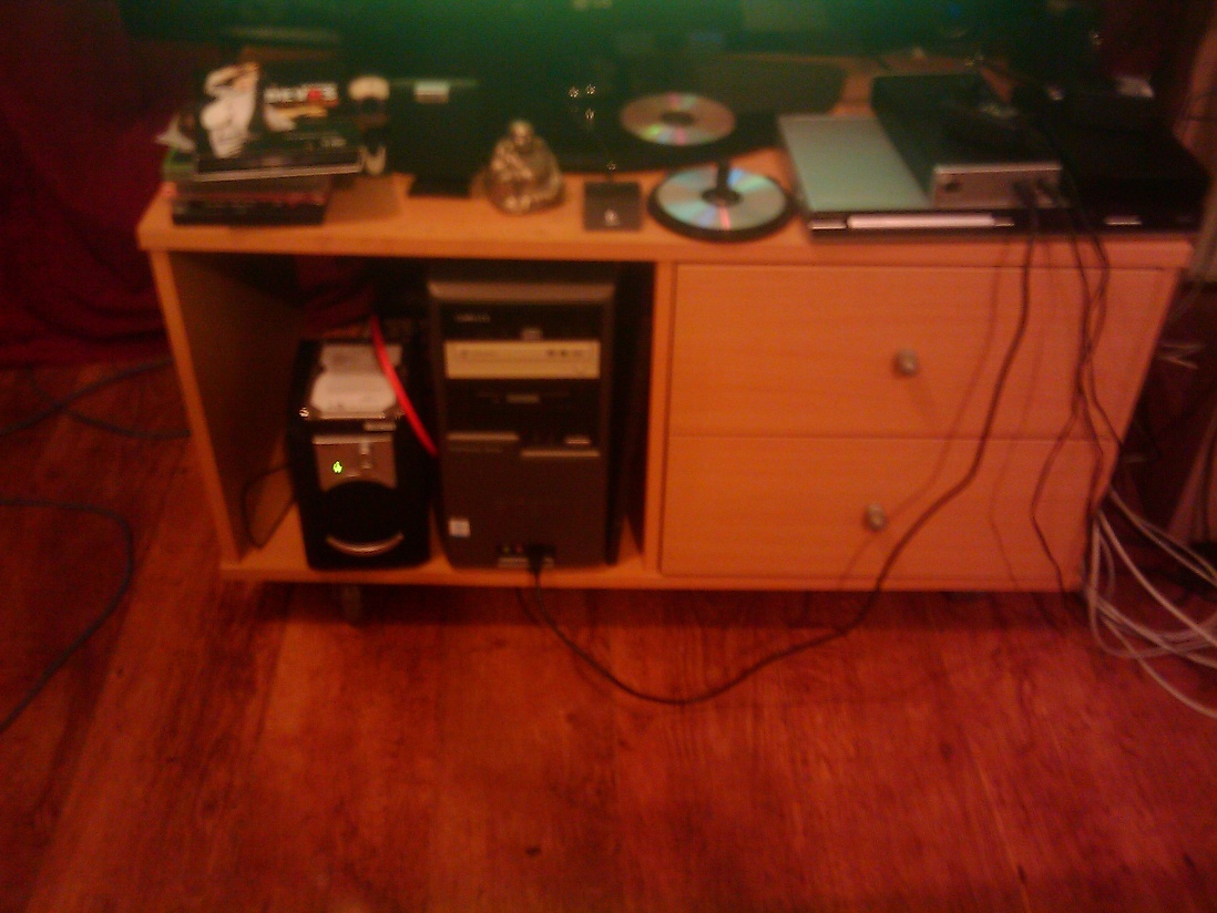
I have always problems with my TV's
furniture to move it because cables stay below the wheels and I have not
enough place to put my computer or any other electronics materials. So, I
will make a furniture big enough to solve the problem I have spoken
previously. Furthermore, I want some decoration on it.
1.1 concept
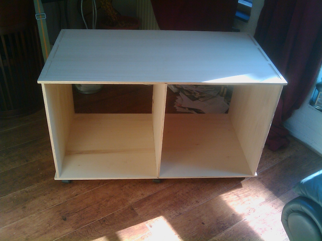
First use the picture of the furniture for which I have problem and then increase the size and think about what type of new cut in the wood, could be helpful to improve the furniture and also to decorate it.
I decided to use almost the full
board that Alex offer us to use to make something big.
A board called sheet industrial
standard = 2,44 x 1,22 meters with a thickness of 12 mm.
1.2.1 First part of the drawing on my laptop
To do that I did use the software
called Inkscape running under Ubuntu 10.04 LTS - Lynx Lucide
I did make 5 drawings to cut my
furniture which will allow me do edit on the Partworks software used
in the Fabalab of Amsterdam.
measure of each pieces:
2 squares ( I will call them Squares) of 60cm * 60 cm, on this squares, the machine will cut 4 rectangles of 1.2cm*3cm spaced out of 16 cm. This will allow to make joints overlapping the 4 pieces which are setting up the furniture.
After that, there are 2
rectangles (I will call them rectangles) of 60 cm * 110 cm. The
machine will cut 3 rectangles holes or pockets 11,128 mm (around 12mm
which is important later during the cut) * 16 cm ( at 1.5 cm from the
edge of the wood). These holes will be separated of 3 cm of wood. I
will add furthermore a path to add another piece of wood in the
middle of the furniture. To do it, I will cut a path of 5mm of depth
and width and 60 cm of length, set at 55cm, in the middle of the each
rectangles.
Finally, another cut 58.8 cm
* 61.2 cm (I will call it non-square as it looks like but it is not).
In this cut, I will make another cut in sharp of “L “, 9,2 cm *
9,2 cm * 3,3 cm * 5,2 cm * 5,9 cm. The first “L” is placed at 16
cm and the second one at 40 cm from the bottom of the piece. This piece of wood will split the furniture in 2 parts.
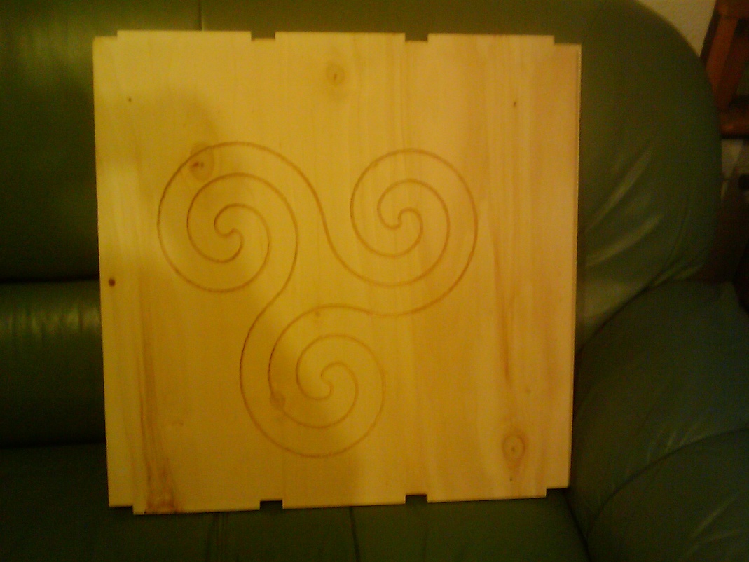
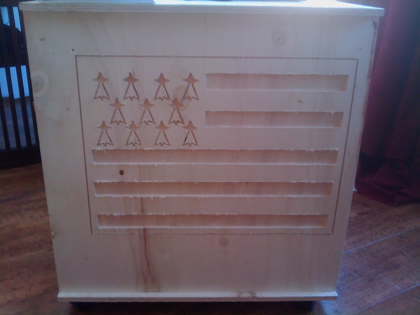
I did add later drawings for the decoration of the furniture. Both drawings were set on the squares of 60 cm. One drawing is the Breton flags and the other one is a triskelion.
breton's flag:
triskelion:

When I open the
file with PartWorks tool to prepare the path that the machine is gone
take to make the cut on the board, it is not working some part of the all
drawing is missing. I did check with other peoples' computer and saw
that on Macintosh computers that my DXF format was not readable also on these
machines.
To make it works, after several tests, I did
finally export my drawing in "pdf" format, version 1.4.
This time it is working. I can see my drawing on the Partworks
software and preparing the path the bit of the machine is gone take
to cut the wood as on my drawings.
1.2.2 Second part of the drawing on the Partworks
When the drawings are imported on
Partworks, I did check if the all measures I have done are respected
as sometimes, it can be a problem when you load a file which has
been exported in a different format that the file which has been first
created.
When this check is done and if needed
some part of the drawings corrected.No problem of size for me but I had to do some change in the drawing just for the cut test.
We can continue the work. Be sure
also not only drawings are corrected but also the size of the piece of
wood you are working on, is set correctly on PartWorks.
In that case it has to be 2,44 x 1,22
meters.
We need now, to have an error free toolpath, so no over lapping and vectors for each drawings need to be closed. Otherwise, it won't works.
Check this with Partworks tool
available and join and remove vectors (see link below for more
advises and help)
In my case, I had a lot of mistakes
(duplicates vectors and opened vectors) but I corrected them. In
fact I should have been able to do it before with Inkscape but it was not
correct. So, I did corrected it. Regarding the decoration, my
drawing was not correct neither on the first time but for them, I corrected
them later on Inkscape and the second time when I load them, they
were all good and can be used directly.
http://www.youtube.com/watch?feature=player_embedded&v=wSHQsthRajg
Once, the drawings are fine, we can start to create toolpath.1.3 First cutting test
If you need some help for
you first step, I invite you to read this link which is providing the
most import information to start to use the CNC router.
http://wiki.fablab.is/wiki/Shopbot
and a lot of links can be
found on this link too, but you have to found out which one is
interesting for you:
http://www.shopbottools.com/index.htm
Now, I can start ShopBot
CNC
console on the computer plugged to the milling machine and turn on the
button of the milling machine and turn on the key. Now, I can start to
work with this machine.
It is very important to follow the all steps (read the checklist of
http://wiki.fablab.is/wiki/Shopbot
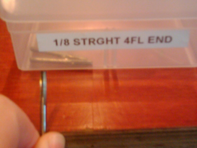
) for security reasons. But before that, you will have to prepare the
machine, by adding the bit. I have decided to use a bit 1/8 straight
4FL end for the cut of the wood board and to use this bit, I need to
use a collet imperial 1/8 to set the bit in the milling machine.
to found out which bit to use, you can check this site:
http://www.onsrud.com/files/pdf/OC-09CatalogR.pdf
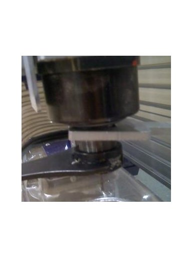
Keys, collet imperial, the bit and spindle
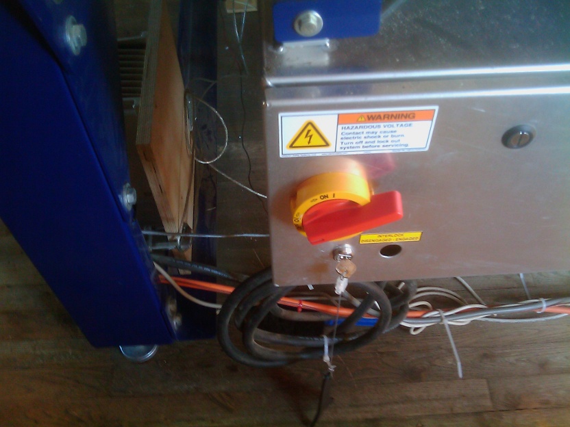
I did install now the bit by using the fixing wrench for shopbot tool holder. New bit can not be add without using these keys. One of those keys is linked to the key which is switching off the milling machine. This means when someone is changing the bit, it is technically not possible for the machine to turn on as it has been switch it off. When the bit is changed, don't forget to set back the key to switch on the the milling machine.
See the key security system in the Amsterdam Fablab
Now, before to go further, I
did set the Zeroing point and set the X and Y value to 0, matching to
the wood board where the bit is set to 0 for X and Y axes.
See below the quick
reference guide for commanding the machine:
http://www.shopbottools.com/files/SBDocs/SBG00109090803CommandQuickRefLaminate.pdf
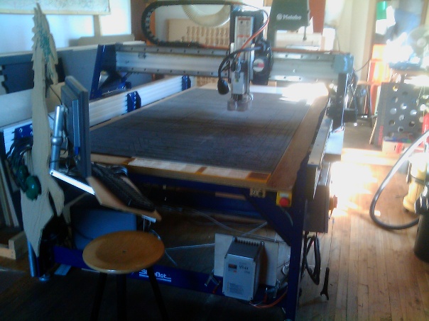
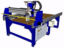
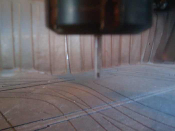
The milling machine
You can see the table where
the cut is occuring, the red button for any urgence to stop, the screen
which is plugged to the computer itself connected to the milling
machine.
This is the machine to make something big :-)
This is very important to
get the drawing cut as it is on the screen. If the values of any of
them are wrong, then the cut won't be done as it should be. In case
of doubt. Set again the values correctly.
XY Origin Position: Most of
the time, it is matching to the bottom left corner. For me it is
also the case regarding the X and Y position.
You can alos use this
document to set it but it is a long document to read:
http://www.shopbottools.com/files/docs/SBG00142080923UserGuide.pdf
or this video to provide you
an idea how to do it:
http://www.youtube.com/watch?v=iznNP9MzzgY
Picture of my tests
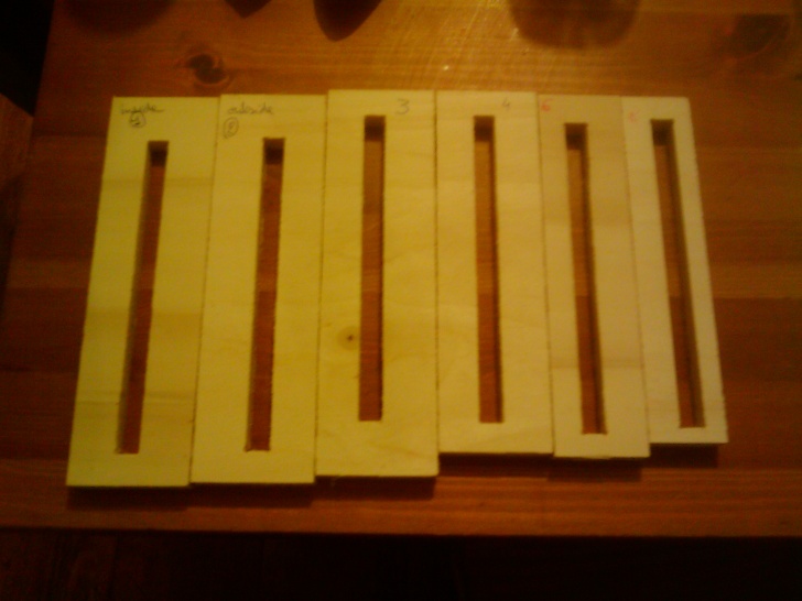
During this test, I figure
out that I needed to set some tolerance when I was doing the pockets
(holes). Indeed, the thickness of the board is 11.80 mm but to be
sure it fit together some tolerance is needed. I mean a pocket (hole)
little bit larger. Otherwise it won't fit. This is the mistake I have
done on several of my tests. I only managed to get the good setting
after 8 tests with some advises from Alex Schaub.
If you want to add or remove extra
material around the vector object, define the distance between the
boundary of the selected vector object and the profiling tool in the
Allowance box. Type a positive value to add material or a negative
value to remove it.
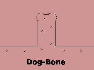
According what I read, the best was to add 1/100 of the size of the thickness. I did also add some “dog bone fillet” on each corner of the pocket which is allowing corners joints to go inside the pocket without any problems. And it is working.
How looks a dogbone
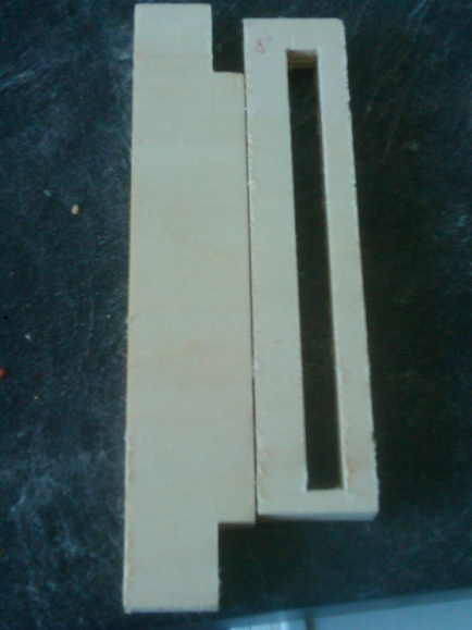
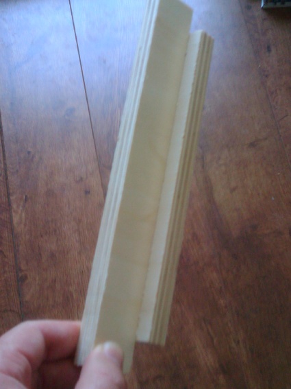
Pictures of the pocket and joints and how they fit together
1.4 Finalising the
drawing according the feedback of the first cutting test
So, I did apply on my
drawings the setting which needs to be set on the pocket. Allowing
later to make sure that the pieces would fit together well at the
pocket joint. As drawing are good now, we can create tool path for
the machine.
1.5 Create the
toolpaths for each part of drawings
When you have selected the
drawing you need, click on the toolpath button on the right side of
the screen.
To get an idea how it looks
and how it work, you can read this link:
http://fab.cba.mit.edu/content/tools/machines/shopbot/
For the all cuts, please
Selected “create pocket toolpath”
Regarding all the drawings matching to
the cut of the furniture, the setting are the same.
I only need to be careful
which part I am cutting first.
Value of the cutting
parameters:
start depth: 0 (starting on
top of material)
Cut dept:13mm
tool:click on select and
set:
First the bit used: 1/8
straight 4FL end
cutting parameters:
pass depth:4 mm
stepover: 3mm
Feeds and speeds:
spindle speed:1200 r.p.m
(round per minute)
feed rate:60 mm/minute
pluge rate:20 mm/minute
Machine vectors:
outside/right
tabs,corners, leads and
ramping. I keep them as there are.
Regarding the drawings'
decoration, I only changed the 3 parameters on the machine
start depth: 0 mm (it did
stay the same)
Cut dept:3 mm
and
cutting parameters:
pass depth:2 mm
stepover: 1 mm
For each drawings, I need to
click on calculate when parameters are set. A warning is appearing,
click “yes”. Then I can click on preview to get a view of what it
will be done by the machine and what should be visible on the board.
At that step, when drawings
are fine, I save them by clicking on the disk icon and the file is
saved under a “sbp” format.
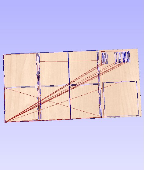
3 D view of the drawings before I saved under "sbp" format and I cut each pieces
When file is saved under
“sbp” format, it can be loaded under the ShopBot CNC (computer
numerical control) console.
As the Z, X and Y values
were already set previously, there is no needs to set it again but if
you have a doubt, please reapplied for Z,X and Y the 0 value. place the bit as it is supposed to be set for cutting corectly.
When we load the file to
CNC console, we have the message with a new window,”continue?”.
Click “OK”. Then, new
message “Now starting router/spindle: click ok to start /spindle
and run the port file”. Well, if spindle is not starting, don't continue. If spindle start to run, then you can click “ok”.
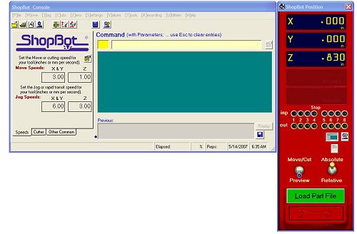
How the shopbot console looks on the screen:
Example of the content of a sbp file:
'SHOPBOT FILE IN MM
IF %(25)=0 THEN GOTO
UNIT_ERROR 'check to see software is set to standard
C#,90 'Lookup offset
values
'
'
TR,12000,1
PAUSE
'
'Turning router ON
SO,1,1
PAUSE,2
'
'Toolpath Name = coupe
'Tool Name = End Mill
(0.125 inch 3.175 mm) (for MDF, layer chair)
MS,59.8,14.9
JZ,20.000000
J3,54.306664,503.063965,6.000000
M3,54.306664,503.063965,-4.000000
M3,149.815948,503.063965,-4.000000
M3,149.815948,598.573242,-4.000000
M3,113.516884,598.573242,-4.000000
M3,113.516884,545.941650,-4.000000
M3,54.306664,545.941650,-4.000000
M3,54.306664,503.063965,-4.000000
M3,54.306664,503.063965,-8.000000
M3,149.815948,503.063965,-8.000000
M3,149.815948,598.573242,-8.000000
M3,113.516884,598.573242,-8.000000
M3,113.516884,545.941650,-8.000000
M3,54.306664,545.941650,-8.000000
M3,54.306664,503.063965,-8.000000
M3,54.306664,503.063965,-12.000000
M3,149.815948,503.063965,-12.000000
M3,149.815948,598.573242,-12.000000
M3,113.516884,598.573242,-12.000000
M3,113.516884,545.941650,-12.000000
M3,54.306664,545.941650,-12.000000
M3,54.306664,503.063965,-12.000000
J3,54.306664,503.063965,6.000000
J3,297.751160,503.117859,6.000000
M3,297.751160,503.117859,-4.000000
M3,393.262238,503.117859,-4.000000
M3,393.262238,598.628601,-4.000000
M3,356.961395,598.628601,-4.000000
M3,356.961395,545.995544,-4.000000
M3,297.751160,545.995544,-4.000000
M3,297.751160,503.117859,-4.000000
M3,297.751160,503.117859,-8.000000
M3,393.262238,503.117859,-8.000000
M3,393.262238,598.628601,-8.000000
M3,356.961395,598.628601,-8.000000
M3,356.961395,545.995544,-8.000000
M3,297.751160,545.995544,-8.000000
M3,297.751160,503.117859,-8.000000
M3,297.751160,503.117859,-12.000000
M3,393.262238,503.117859,-12.000000
M3,393.262238,598.628601,-12.000000
M3,356.961395,598.628601,-12.000000
M3,356.961395,545.995544,-12.000000
M3,297.751160,545.995544,-12.000000
M3,297.751160,503.117859,-12.000000
J3,297.751160,503.117859,6.000000
'Toolpath Name =
droitedecoupure
'Tool Name = End Mill
(0.125 inch 3.175 mm) (1)alu
TR,12000,1
MS,59.8,
J3,589.582336,600.186096,6.000000
M3,589.582336,600.186096,-3.000000
M3,589.582336,-0.226314,-3.000000
J3,589.582336,-0.226314,6.000000
J3,589.582336,600.186096,6.000000
M3,589.582336,600.186096,-6.000000
M3,589.582336,-0.226314,-6.000000
J3,589.582336,-0.226314,6.000000
J3,589.582336,600.186096,6.000000
M3,589.582336,600.186096,-9.000000
M3,589.582336,-0.226314,-9.000000
J3,589.582336,-0.226314,6.000000
J3,589.582336,600.186096,6.000000
M3,589.582336,600.186096,-12.000000
M3,589.582336,-0.226314,-12.000000
J3,589.582336,-0.226314,6.000000
JZ,20.000000
J2,0.000000,0.000000
'Turning router OFF
SO,1,0
TR,0,1
END
'
UNIT_ERROR:
C#,91 'Run file
explaining unit error
END
Once each toolpath is
created for each drawing and saved in “sbp” format.
We
need to run the machine
and cut the pieces as planned. The file logs visible above are show
what type of information the milling machine is using to make the cuts.
1.6 Order of the cut and the decoration
1- The 2 squares
2- The pockets of the
rectangles are done before the rectangles because otherwise, when
rectangles are cut, the loose won't allow the machine to cut
correctly the pockets. So, this is the reason, I start by the pocket
(or holes)
3-The path of 5mm of depth
and width and 60 cm of length set at 55cm, in the middle of the each
rectangles.
4-The non-square
5- After I make 4 drills in
the non-square piece of wood. Machine can cut the sharp of “L “
in the non-square.
6- After I make 4 drills
in the one of the square piece of wood. Machine make the Breton flags
7- After I make 4 drills
in the one of the square piece of wood. Machine make a triskelion
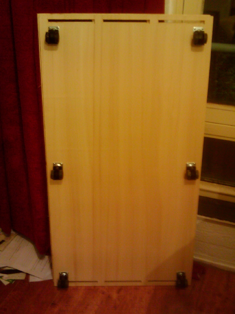
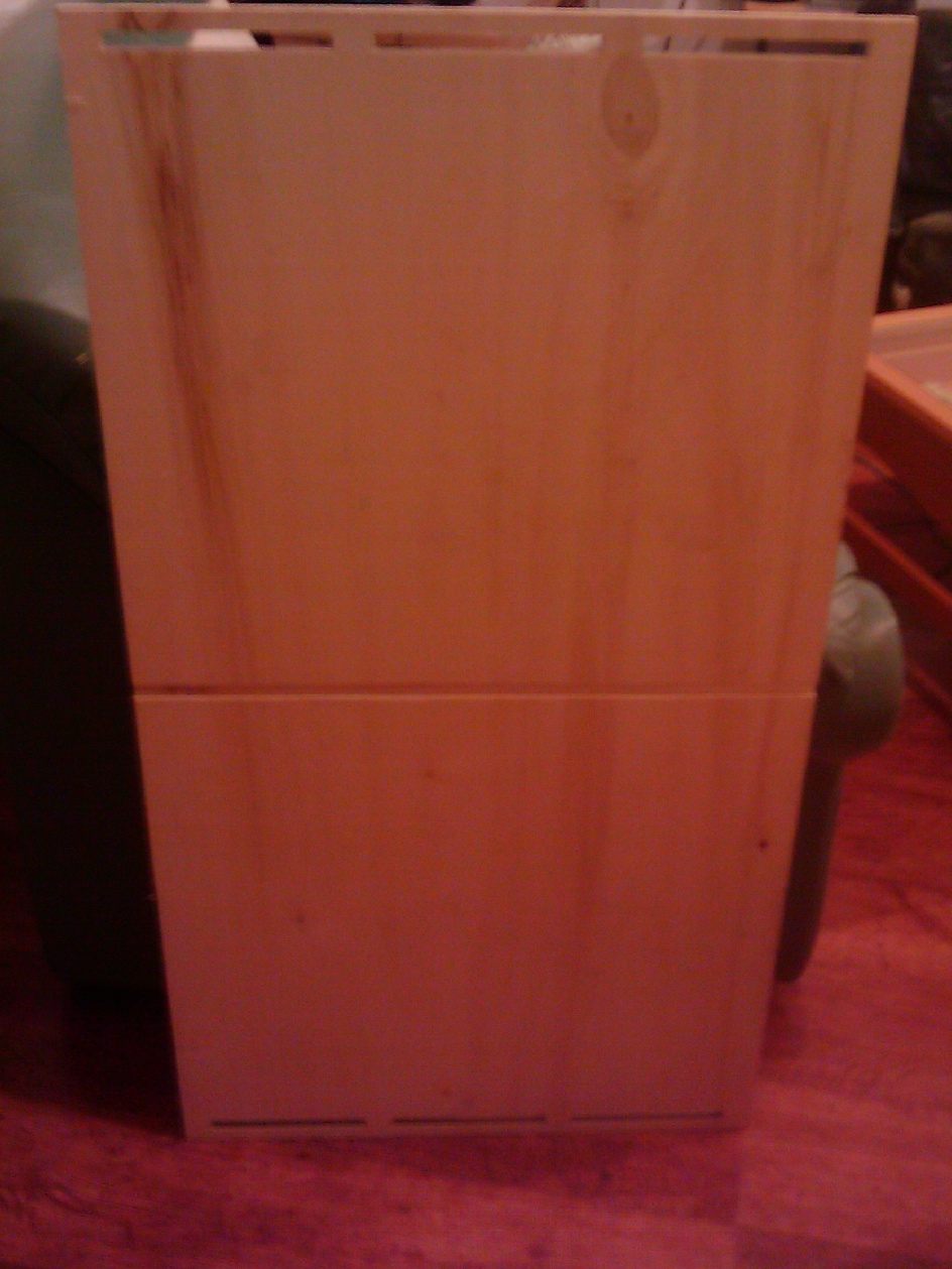
2 the pieces of wood cut, decorated and all fit together and the wheels added