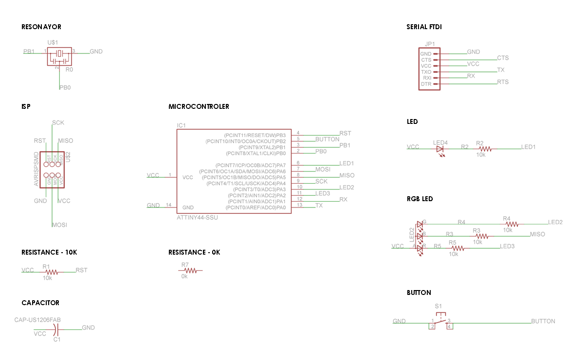
Components
The PCB was designed in EAGLE.
All libraries are posted on the course, except the SERIAL FTDI that is in the library sparkfun.lbr and the LED that is in adafruit.lbr.

The BOARD button is attached to PB2.
The RGB LED is attached to PA2, PA3, PA5. Because PA5 is MISO, the Blue LED's blink when the board is being programed. The LED's are setup in inverse mode, so when the PIN is HIGH, there is no path to GND
The cathode of the LED, the LED is off. When the PIN is LOW, then because the micro is connected to ground, current flows and the LED lights on.
Design board
The hardest part is the generation of board, but always follow the same logic, in the schematic only matters who is one with whom, on the board only as are joined.
Suggestion, almost all components must be connected to VCC and ground, place them around the board so it is easy. In my case I use a bridge, using a resistance of value 0.

For generate the design i use the command "autoroute" with the configurtation:
Routing Grid - 40
via shape - Round
1 top - /
16 Botton - N/A
That was not perfect and there were some conections wrong, it was necessary to redraw the route manualy. Finally connections use 0.5mm thick, because they were too thin 0.4mm pear soldier
Milling

After the schematic and board, image export, Eagle has a menu option to "export", selected as a image, monochrome, and 500 DPI.

Soldering
The final board.


