FabLab Academy 2012
Manchester Lab
David Forgham-Bailey
Weekly Assignment:
The task this week was to read the Data Sheet for the ATTINY 44a,
then
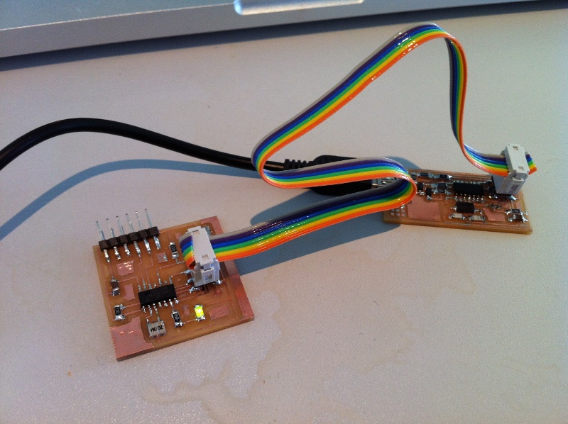
program the modified hello board which we made in week 7 using a number
of programming languages.
Narrative:
I had a feeling that my original board was defective, and while
attempting to resolder, the tracks began to lift from the backing
board. So, I took the opportunity to redesign the board in Eagle, and
mill a replacement with the Roland Modela. This time I fitted a new tip
to the soldering iron and found stuffing the board much easier. The
board worked first time.
I used the Arduino Program first, following the detailed tutorial to
establish that the system was working. This was relatively straight
forward. I ran the bootloader ahving set the board to ATTINY44 @20mhz
and the programmer to USBtinyISP. Then I wrote a simple routine
of my own to make the LED Fade in and out when powered up, and change
to Blink when the button is pressed:
/*
button_led_blink_fade
Turns on and off a light emitting diode(LED) connected to
digital
pin 7 (6tiny), LED blinks when pressing a pushbutton attached to
pin 3 (10tiny).
fades in and out when button released
The circuit:
* LED attached from pin 7 to ground - attiny44 pin 6
* pushbutton attached to pin 3 from +5V -attiny44 pin 10
* 10K resistor attached to pin 3 from ground
created 2012
by dfb
*/
// constants won't change. They're used here to
// set pin numbers:
const int buttonPin = 3; // the number of the
pushbutton pin
const int ledPin = 7; // the number
of the LED pin
// variables will change:
int buttonState = 1; //
variable for reading the pushbutton status
int brightness = 0; // how bright the LED is
int fadeAmount = 5; // how many points to fade the
LED by
void setup() {
// initialize the LED pin as an output:
pinMode(ledPin, OUTPUT);
// initialize the pushbutton pin as an input:
pinMode(buttonPin, INPUT);
}
void loop(){
// read the state of the pushbutton value:
buttonState = digitalRead(buttonPin);
// change the brightness for next time through the loop:
brightness = brightness + fadeAmount;
// reverse the direction of the fading at the ends of the fade:
if (brightness == 0 || brightness == 255) {
fadeAmount = -fadeAmount ;
}
// wait for 2 milliseconds to see the dimming
effect
delay(2);
// check if the pushbutton is pressed.
// if it is, the buttonState is HIGH:
if (buttonState == LOW) {
digitalWrite(ledPin, HIGH); // set the LED on
delay(250);
// wait for a second
digitalWrite(ledPin, LOW); // set the LED off
delay(500);
// wait for a second
}
else {
// turn LED off:
analogWrite(ledPin, brightness);
}
}
Next I used a Terminal on my Mac and used gavrasm and avrdude to
compile the hex file and program the chip.
Assembly language program:
prog name (describe the process)
copyright info
Hardware info
Ports and Pins
Register Definitions
Macros
Interrupt Routines
Sub Routines
Main Program
commands:
gavrasm program_name.asm
- creates program_name.hex
avrdude -p t44 -c usbtiny -u flash:w:program_name.hex
- command line to program the chip
avrdude -p t44 -c usbtiny -u lfuse:w:0x7E:m - to set
the fuses.
Comments:
Software: - I also tried AVRStudio ( I dug out my
old Windows laptop and installed AVRStudio)
Hardware:
Materials:
Machine Settings:
Photos:
Files:
Drawings:
External Links:
Course Notes:
von Neuman - software that can
RISC - Reduced Instruction Set - /speed and predictable timing/
CISC
microprocessor
desktop
FPGA (GATES)
microcontroller - many different types of memory - I/O - system on a
chip
RISC Microcontrollers - (ATTINY44A) -
register - used when doing instructions
SRAM - saving/stores dynamic
DRAM -
EEPROM - stores when switched off
FLASH - Non -volatile - programs
fuse - for configuration - sets up processor
peripherals - word size - families -
ATMEL AVR - designed from ground up - RISC instruction set - DCC
directly supports AVR - GOOD instuction set - WIDE FAMILY form cheao
and small to big and complex -
DATA SHEET
packages - DIP / SOT / SOIC (small outline)
clocks - RC / ceramic / quartz (best resolution)
programmers
ISP / ICE (in-circuit emulation) / JTAG debugwire - realtime acess to
processor sets up breakpoints etc / debugging in the system /
bootloader - programme which loads programmes
AVR Libc
gcc - install these in Linux avr-libc/binutils/gcc-avr (c development
environment)
host communication RS232 / Kermit minicom / FTDI cable (RS232 to USB)
languages - c / c with interupts / assembly /
IDE _Integrated Development Environment
AVRStudio - Eclipse - Arduino -(set of c libraries - IDE - lets you
program and load - boot loader - standard set of boards)
david mellis - arduino
interpreters - Python / Basic / Forth / AVRSH
Eddies lecture -
registers - address in hex content in binary - *.asm (assembly
language)