0 / Final (Art) Projects :
After a lot of tests, I had to abandon my first final project 1. To see a working project, please refer to Final Project 2 on this same page.
1 / Final (Art) Project 1 :
Trying to run video displays with Arduino is not possible. It requires another kind of board : FPGA or ARM. They have enough RAM, and Arduinos don't. My final project 1 is more like a succession of tries to make an Arduino Mega 2560 work with 3 different displays. I use the Mega 2560 to test the displays, and when I know how it works, I connect them to the FABDUINOS I made (I have 3 of them).
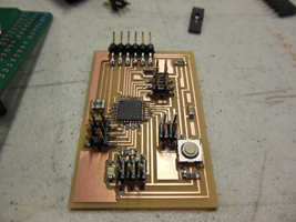
The FABDUINO's microcontroler is an Atmel 328, 3.3 V, 8Mhz. Mine has 26 pins available. I have 2 other fabduinos with less pins. I use the one with more pins because displays usually need a lot of connections. I've also made a 5V power board to provide more juice to the displays.
The first display is a graphic liquid crystal display, the GLCD KS0108 (128 x 64). It's cheap and commun (25 $) and I actually managed to run arduino sketches on it with the Mega 2560, and even on the FABDUINO. The second one is a Vacuum Fluorescent Display GP9002A01A from Futaba (128 x 64 bit). It's expensive (95 $), good looking, but it needs a lot of energy to work. It hasn't shown any light while connected to an arduino board until now. I can hear a kind of sound coming out from it but the screen stays blind. The third one is a 128 x 32 OLED Display Module UG-2832HSWEG04 (17.5 $). It's not showing light either. They were all ordered from Adafruit.
1 / 2 / About adafruit's tutorials :
Except with the KS0108, tutorials are very incomplete and even contradictory sometimes. I have been reading a lot of datasheets to make those display work, making connections after connections, moving a wire to another pin, removing all the wires and starting again with a new pinmapping.
1 / 3 / Things that worked
Like I said, the FABDUINO and the KS0108 kind of worked together. I could show Arduino sketches like the 8-bit video game "Rocket" or the animation named "Life". Nevertheless, parts of the display were not showing anything while the bitmaps were running on other parts of the screen (line cuts).
I also added a coin acceptor to the blue case I am using for my final project. I made a hole and clipped the 2 parts of the coin acceptor on the case's surface, like a sandwich. This coin acceptor can receive any kind of coins until a Quarter. To configurate the coin acceptor you need 30 samples of a same coin. You push on the reset button and an LED starts to blink. You insert the 30 coins one after the other. When the LED stops shinning, it means the coin acceptor is ready to work. The OLED is supposed to display a message every time someone inserts a coin. It's not operative yet.
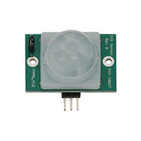
I have tested the PIR sensor with the FABDUINO and it's working very well. I am planning to use it to start the coin acceptor when someone comes around the case.
Here is a list of the questions the preparation of this assigment should answer to :
  Plan and document a final project that integrates the range of units covered :


  1 - what will it do ?

  This is an artwork hosted into a case. It will display videos of the french theory authors on a
  screen every time someone will stand around the case.

  2 - who's done what beforehand ?

  Someone used a graphic LCD as a video display run by Arduino. See this page chibimo or this video.

  3 - what materials and components will be required ?

  An Arduino board, an INFRARED sensor, and a graphic KS0108 LCD 128x64 + extra … or eventually a
  vacuum fluo display.

  4 - where will they come from ?

  I will use the arduino I made in class. The other components will come from adafruit and
  parallax websites.

  5 - how much will it cost ?

  35$. The use of a vfd will put the price up to 129 $.

  6 - what parts and systems will be made ?

  The Arduino will be made. A chess game will be laser-cut from blue mirror acrylic.

  7 - what processes will be used ?

  Board-milling on Modella. Board soldering. Arduino programation. Laser-cutting on Epilog.
  Wax casting for the chess game. Video formatting with AE CS5 or Streamclip for the video contents.

  8 - what tasks need to be completed ?

  I need to make a new Hello_Arduino_board. I need to connect the motion sensor to it, as an input.
  I need to connect the display as an output. Then I need to program the arduino to make it start
  playing videos when someone comes around the case. Then I need to cut a hole into the case to
  insert the display. I also need to cut en raster the chess game on the laser cutter and to make it
  fit into the case.

  9 - what questions need to be answered ?

  I need to know if the Arduino clock is fast enough to run my video. I need to make it from a mac
  whereas the examples were mad from a Windows PC. I also need infos to go further. I want to play
  sound into 8 headphones. I also want to add a power button to the case as well as a beacon.

  10 - what is the schedule ?

  I'll work on this project since I have the components, that is to say from today (may 16th, 2012)
  until may 25th.

  11 - how will it be evaluated ?

  The project will be evaluated on the basis that the french theory's videos are displayed when
  someone approaches the artwork. Also on the quality of the chess-game.
  This is all about aesthetics and function.

  Projects can be separate or joint, but need to show individual mastery of all of the skills where
  possible, you should make rather than buy the parts of your project
2 / Final (Art) Projects 2 :
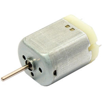
Here is a working project. This project is very simple. A PIR sensor is connected to a DC motor, and the motor starts to turn every time some mouvements are detected by the PIR sensor. The motor keeps moving as long as mouvements are detected. I was provided an excellent tutorial from Bildr to do so.
Plan and document a final project that integrates the range of units covered :
1 - what will it do ?
This is the electronic part of an artwork. A DC motor will start turning everytime mouvement is detected by a PIR sensor.
2 - who's done what beforehand ?
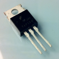
Someone posted a project on BILDR to connect an ARDUINO to a TIP120 Transistor.
3 - what materials and components will be required ?
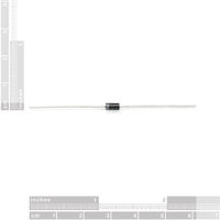
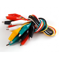
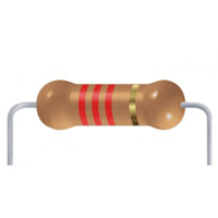
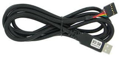
A FABDUINO board (atmel 328, 3.3V, 8 Mhz), 1 PIR sensor (Paralax), 1 TIP Transistor 120, 1 1A 50V rectifier diode, 1 resistor (2.2KΩ), 1 FTDI cable, 5 jumper wires, and 1 12V power supply.
4 - where will they come from ?
I will use the arduino I made in class. The dc motor, the 12V charger (recycled), the 2.2KΩ resistor, the FTDI cable and the jumpers are from the lab. The PIR sensor will come from Adafruit, the TIP120 transistor will come from Radioshack as well as the 1A 50V rectifier diode.
5 - how much will it cost ?
It will be very cheap.
6 - what parts and systems will be made ?
As I had to figure out this second final project after the fab academy program finished, as I will be mouving back to France in a few days, I have limited my final project to the completion of the electronic part. Besides that, I will test a 3D design for a wall support on the Makerbot (7h00 for a 25% fill). The motor will be blocked into it, in a special comb based on its shape. I will also test the arty part of this project with the laser-cutter, on acrylic sheets.
7 - what processes will be used ?
Board-milling on Modella. Board soldering. Fabduino programation. (+ 3D printing on Makerbot, Laser-cutting on Epilog, plastic casting)
8 - what tasks need to be completed ?
1 - I need to make a new FABDUINO, and I need to burn it with the Arduino software. 2 - I will solder 2 wires to the dc motor to solder the diode on them. I will put tape on the 2 wires to remember which one is power (red) and which one is ground (black). Same thinf for the power supply. 3 - I will solder the 1A 50V rectifier diode on the DC motor. There is no + or - on this type of motor. Nevertheless, once soldered on the motor's wires, the diode's Catode will have to be directly connected to the Power supply, and the Anode will be directly connected to pin C of the Transistor (middle pin). 4 - I will connect pin B of the transistor to the FABDUINO'S pin 9, with a 2.2KΩ resistor in between. I will use jumper wires to do so. 5 - Pin E of the Transistor will be conneccted to the FABDUINO's Ground, and to the power supply's ground with jumper wires. 6 - I will connect the motion sensor to the FABDUINO as an input with jumper wires to pin PWM 11, to VCC, and to Ground. 7 - Then I need to modify the sketch to program the arduino so as to make it start the motor when movement is detected by the PIR sensor.
9 - what questions need to be answered ?
10 - what is the schedule ?
I'll work on this project since I have all the components. Once every parts are available, it shouldn't take more than 1 day to make it work.
11 - how will it be evaluated ?
The project should show how movement detected through the PIR sensor starts the motor.
Projects can be separate or joint, but need to show individual mastery of all of the skills where
possible, you should make rather than buy the parts of your project