Computer Controlled Cutting |
|
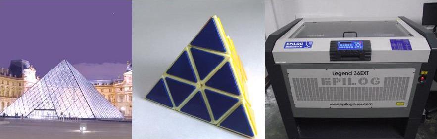
This week assignment deals with design and make a press fit construction kit, using a laser cutting tool. I was inspired by models of pyramids shown in the Figure. So I decided to build a pyramid with equilateral triangles and four faces, because an n-sided base will have n + 1 vertices, n + 1 faces, and 2n edges. |
|
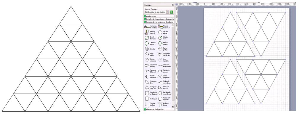
First I used Microsoft Visio to make a rapid sketch to define the dimension of each face of the pyramid and the dimensions of single equilateral triangles |

|
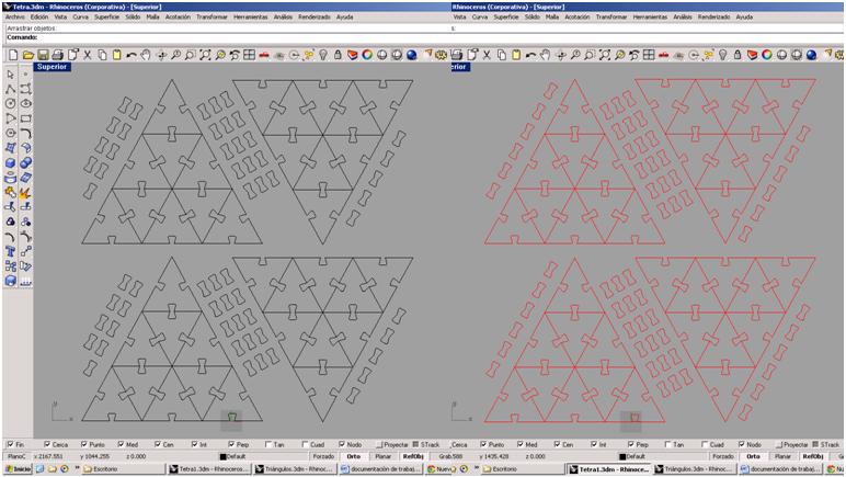
Draw with Rhino of the individual triangles and the press fit piece |
|
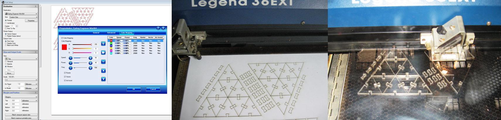
The final design (in red). Considering the offset of the laser beam I had to resize the press fit piece to compensate for laser beam cutting |
|
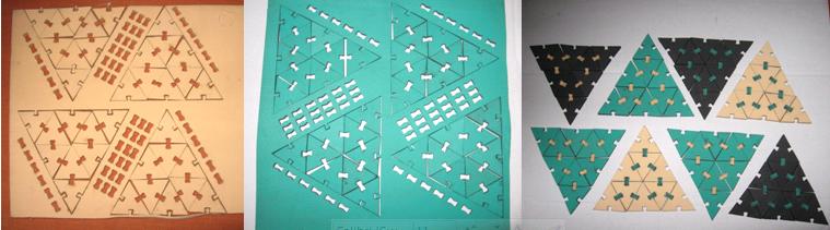
Another two laser cuttings, in cardboard for models and in acrylic.
Laser cutting, parameters for acrylic are, speed=10, power=100, frequency =500, resolution=600 |
|
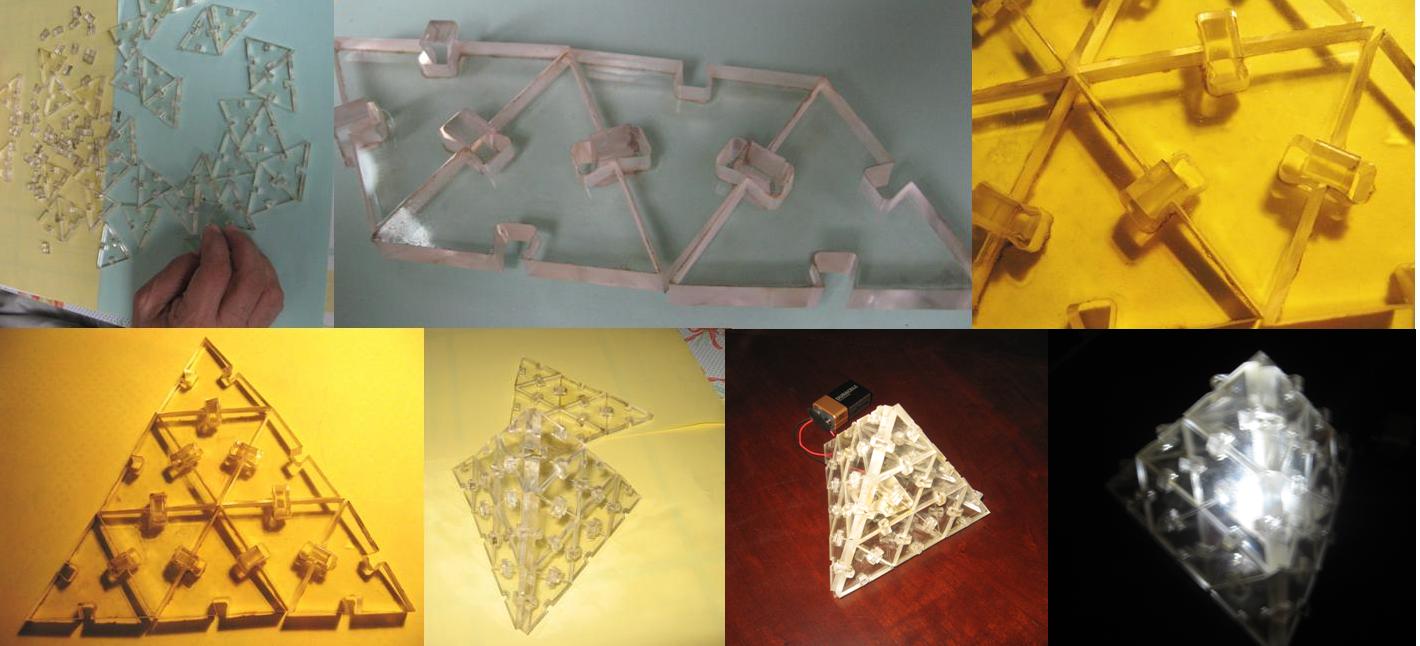
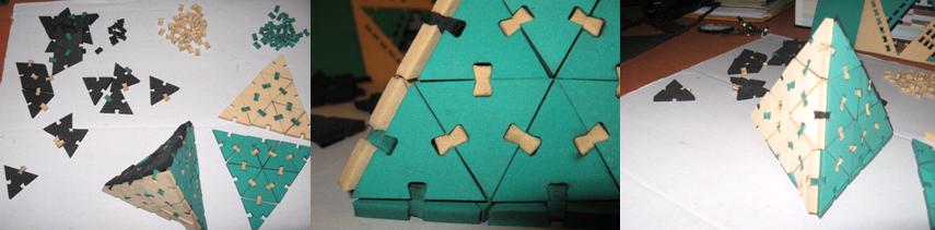
Laser cutting of the kit. I used a soft foam and the assembly of the pyramid faces was easy, because the foam stretched a little when I placed the prees fit piece to joint the individual triangles |
|
But assembling together the faces of the pyramid was not easy, because for this purpose the press fit piece was to much soft. I`ll try with other materials for this type of joint. |
|
Tetrahedron's assembly and installation of the darkness sensor designed at the end of this assingment |
|
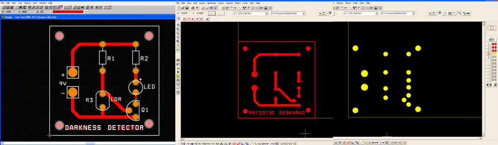
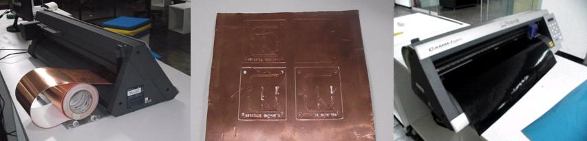
Also I designed a pcb with OrCAD and generated a Gerber file and export it to Corel for cutting solder side and solder mask of the pcb |
|
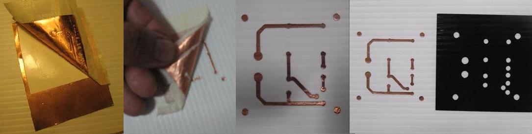
Vinyl cutter, cutting copper clad solder side and vinyl for a solder mask for the previous design. This was really a test, because I must use some film for preparing a silk screen frame. This procedure could also be use for preparing a stencil for applying solder paste to SMD |
|
I made the transfer of the copper clad on plastic cardboard. It's something difficult, but helps a lot if you make some cuts to the copper to be removed. |
Final Comments: I'm just beginning to explore laser and vinyl cutters. I also prepared some draws for engraving acrylic with the laser cutter, and I think that could also be used for engraving pcb. |
Thank you |