The assignmente for this week is to automate the machine assembled two weeks ago. For this Roxanna milled the Arduino's shield for controlling the steppers, but Alejandro found that we haven't all the components for stuffing, specially the A3982 - stepper motor driver, so as was impossible to get it locally, I decided to design a new one using the L298 (Dual full bridge drive) because it has also the possibility to work with the Arduino Uno at the Fablab.
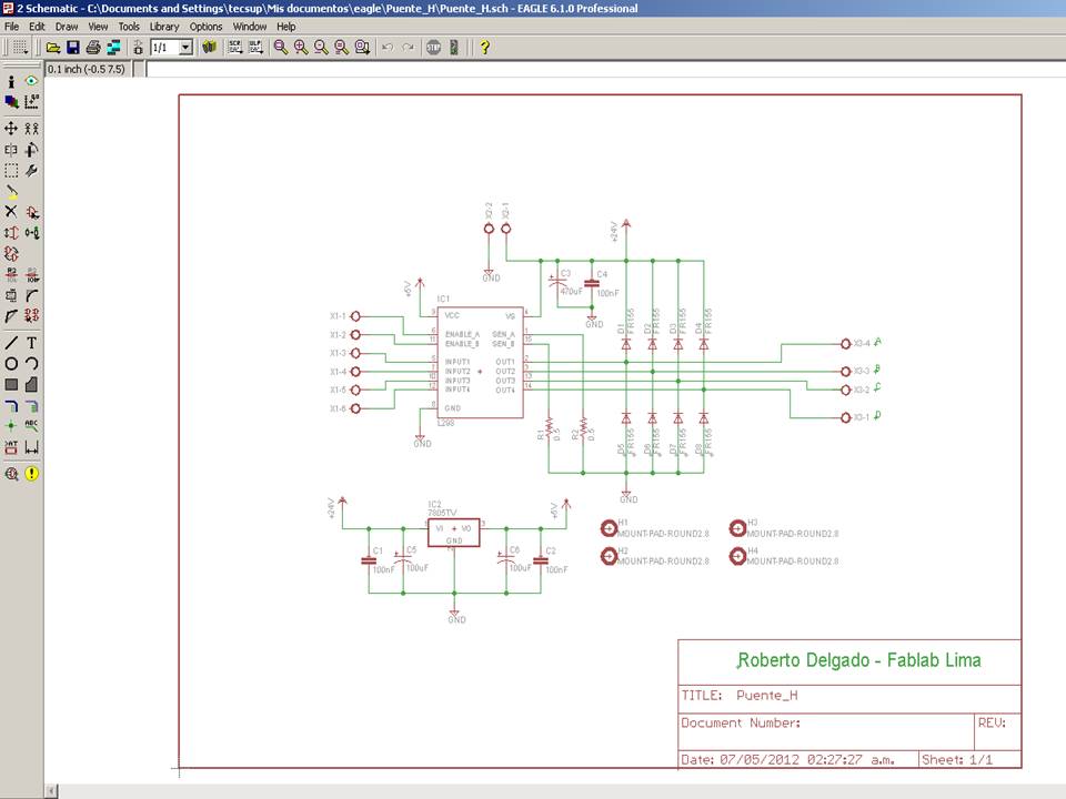
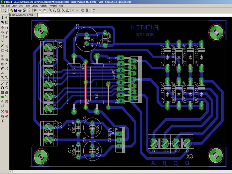
The Eagle board design file is H-Bridge
Figure 1. The H bridge schematic and board designed in Eagle
Then we stuffed the boards with through holes, with components got locally. Following we test the Switching PS, and connected to the H- bridge boards, connected the Arduino to the boards and to the computer. I also downloaded and installed all the needed software, and were ready to test; but we have to modify the software for controlling the new boards because they have more connections to the Arduino. The pictures below shows some activities realized, the first one shows the original board and the replacement boards.
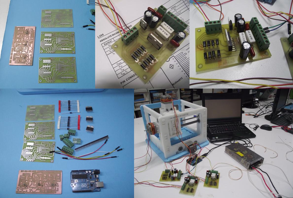
Figure 2. The boards (three boards for the L298 H bridge and one for the Arduino's shield stepper driver), the components, the boards assembled and the machine with the PC and the switching power supply.
At this point we had to leave the machine to the other groups for disassembling and fulfill their assignment. Then I continued with electronics to move the motors.
I couldn't use the Arduino because it was out of order, so I should try another design and worked with a PIC18F4550 microcontroller. I searched the web and found this schematic simulated in Proteus. It uses a Maxim's Max232 IC for comunications with the PC, and 18F series PIC. I build the block diagram from the schematic.
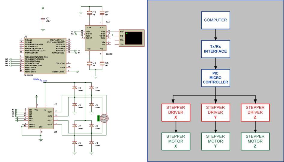
Figure 3. The schematic and the block diagram for the control using the PC and a PIC microcontroller
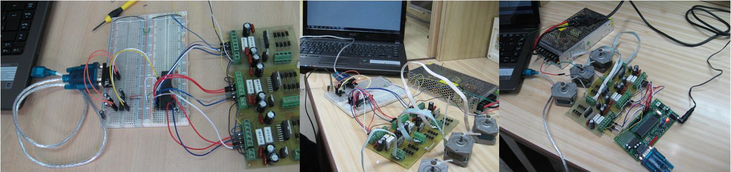
Figure 4. The picture of the left. shows the prototype of controller with a PIC 18F4550 and the H-Bridge drivers conected to the computer, in the picture of the middle is the completed system including motors, power supply and PC, in the picture at the right I used a LAB-X2 Experimenter Board for the PIC instead the of protoboard.
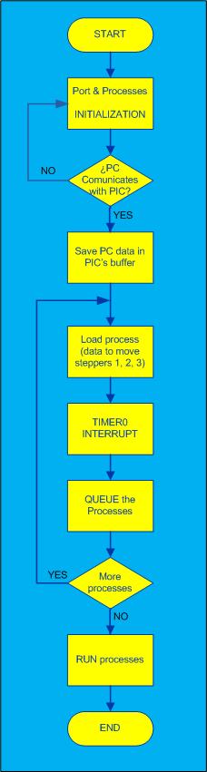
The next figure shows the block diagram (made in VISIO) of the program implemented in C to move the steppers. I'm including the code also.
http://channel9.msdn.com/coding4fun/articles/Computer-Controlled-Stepper-Motor
This work has been too long since we had no materials to build the electronics of the MTM. On the other hand, I had to do my best to accomplish the assignment and that is very rewarding.