
Home >Class May 3 Assignment
Group assignment that we decieded to take on is making a visually pleasing doorbell indicator.
The machine consists of a master and (x) slaves
The master get's a signal form the doorbell, after which it commands the slavves to go to different positions the nodes will signal to the master that they're at the designated position by letting go of their tx lines.
The master has a pullup enabled on it's rx line so it can see when all slaves are done executing the command, after which it will send the next command intill the doorbell stops ringing.
When the doorbell stops, it will tell the slaves to return to their home position.
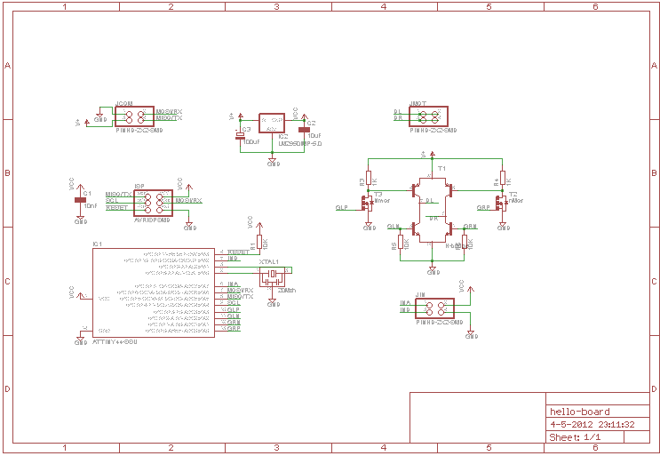
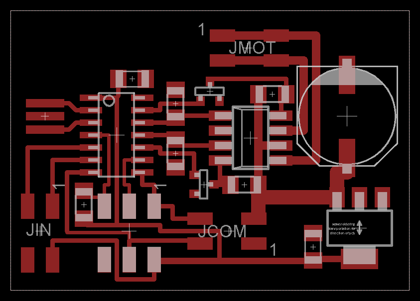
For my slave board i've rolled the node example and the h-bridge example into one. The 2 remaining unused pins are brought out to another pinheader and will be used to provide the input for my closed loop system.


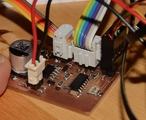
Input is going to be taken from two optical slot sensors. These will be placed over a gear/ slotted disk in the system, a little offset from each other. This way my board will be able to tell which way the motor is turning as well a how far it has moved. Also if the contraption is being moved by something else than the motor, it can update the current position.
My program accepts the following command:
First the node id ('x' for my board)
then the direction (a/d: forwards/backwards respectively)
the distance concluded by a space
then the speed again followed by a space
premature stops can be implemented by sending the ID twice (eg. xx)
'xa2584 128 '
so the above takes the contraption 2584 steps backwards at half speed.
automation.44.c automation.44.make
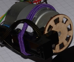
Currently the setup is only using one optical slot sensor. this one is connected to Int0 on the microcontroller. This way counting and controll can be done whilst waiting for incoming controll characters.
The drawback from this is that the direction becomes undetectable. This could be remedied however with incrementally vareing slot sizes. (small medium large to small again in the forward direction)
Due to time costraints this solution is not implemented.
Linear motion from a dc motor. positional feedback on motor (circle of wood with optical slots, or directly from the gearteeth. This depends on the dc-motor used.)
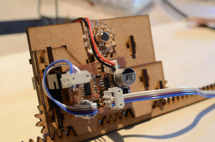
Scavanged printer parts: dc-motor, gear and toothed belt.
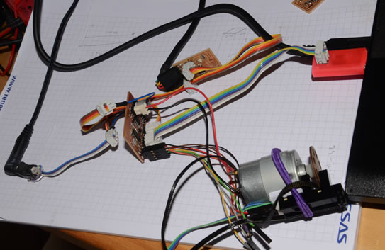
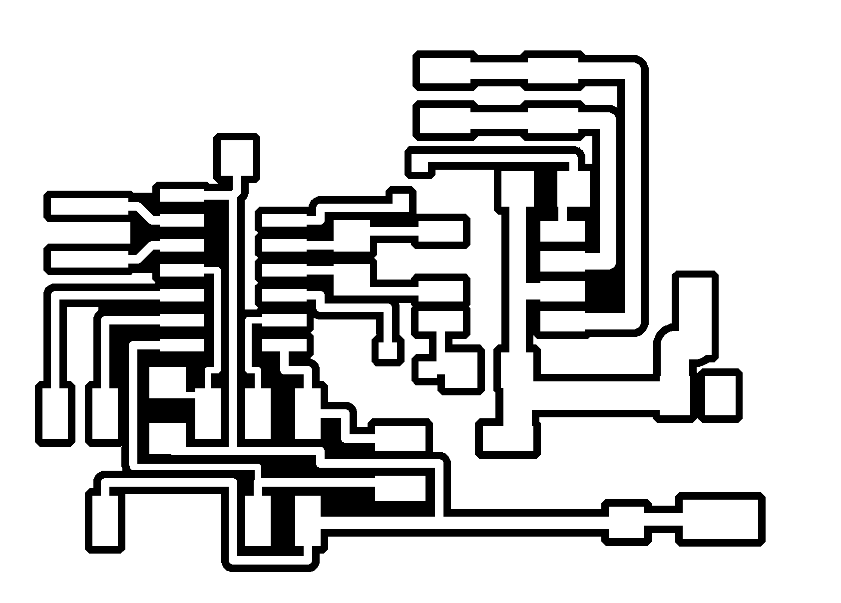
automation setup (to be connected to the mechanical part)
Connected result:
