
Home >Class Feb 15 Assignment
I like the idea of the milled-out usb-connector, and after i filled out my first one, i got some inspiration to enhance it.
I wanted to center the isp connector and add some led's for status feedback
For the leds wanted a power-led and a activity indicator. Both were easy enough to implement because both the CLK line and the VCC were readly available near the ISP connector.
I also removed the solder-jumpers from the design because i figured that i could also just cut the lines with an exacto knife after the programming.
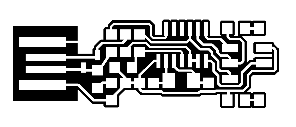

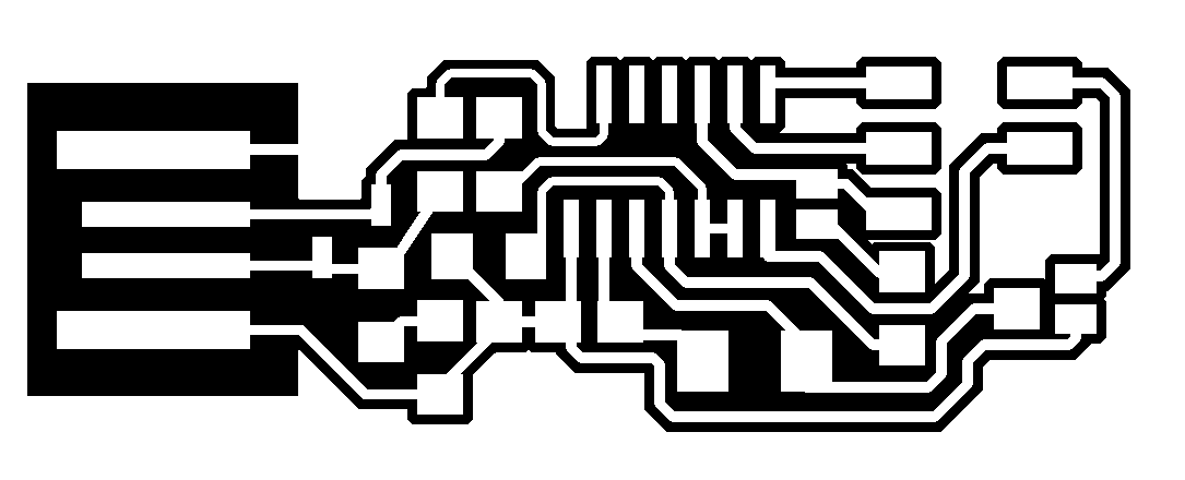
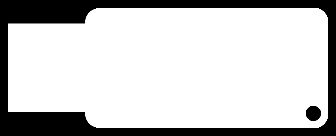
After i build my iteration of the board with Cadsoft Eagle, I exported it to png. I then used the Fab-Modules to generate the toolpaths for the Modela.
I milled and solderd my board without any notable difficulties.
After that i compiled the firmware (using winavr) after making sure the makefile was set-up the right way (this design uses a 20 Mhz crystal).
I used the MKII from Atmel to program the code on the ATTiny44A (t44 for avrdude). To actually be able to use the MKII with AvrDude i also needed to install LibUSB-Win32.
After programming the ISP i cut the line between pin6 and the reset pin, and also decided to cut the vcc line between the ISP and the led that i added. so now the led will be turned on by power coming from the target board. This also acts as a visual check that the target board is connected right and is powerd.
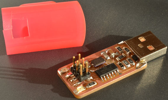
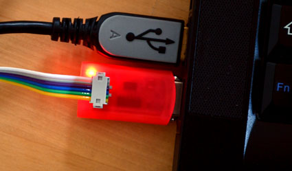
After i got home i pimped it a little by adding the metal usb plug surround from an old usb plug and a scavanged cover from a usb-stick to cover the print and provide a plug cover.
ideas for casting and molding: cast this in plastic.