SUMMARY
Like many of our colleagues around the world, we went through a lot of bits this week on the Modela. In addition, we tried to save time by milling out multiple boards simultaneously on a 4 x 6 FR1 sheet, which often resulted in the incomplete routing of traces on the boards. These boards had to be manually trimmed in limited areas with an exacto blade to conform to the desired circuit board output. Typically, the very narrow traces between pads, or a ground or voltage line at the outer margin of the board would require some attention.
Incomplete routing was not an issue when boards were cut one at a time using the fab modules.
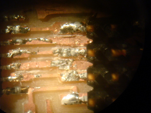
View of J3 on LCD board, showing areas trimmed with exacto blade to separate traces missed by Modela.
DISCUSSION
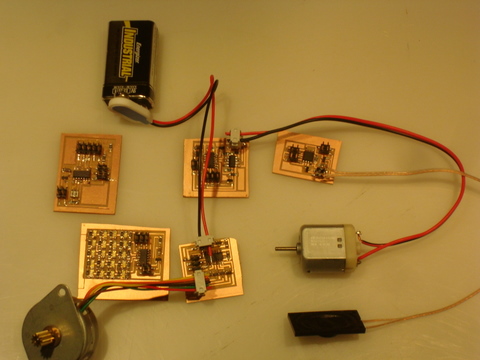
Soldering these mini circuit boards is becoming easier, now that we have put together about a dozen of them. Also, we are beginning to see the similarities and differences between the boards and the programs which run them. As I was racing through some of the mechanics of assembling the boards this week, I found it was easy to confuse a voltage regulator for a MOSFET, as they both had the same physical footprint, and differed only by identifying number/letter codes lightly impressed on the upper surface. I misstuffed one board by soldering in a MOSFET where a voltage regulator should be, which gave off an acrid puff of smoke when I tried to program it, and so far, an unusable board.
Also of note, the boards usually became pretty warm when they were plugged into the ISP. We moved fast, and then operated the boards with a battery. We have our ISP configured such that they still supply power to the target board.
To program the boards, we typed the following in the terminal window:
sudo make -f hello.XXXX.4*.make
sudo make -f hello.XXXX.4*.make program-usbtiny
The boards this week used the AVRtiny44 or AVRtiny45 - an asterisk acts as placeholder for "4" or "5". "XXXX" refers to the input board you are using (for example, "RGB" as in hello.RGB.45.make).
One of the revelations come late to me this week is that in an embedded system, the program is always on in an infinite loop when power is applied with a while(1) statement. This would imply that everything one would want a chip and circuit to do has to be programmed in advance, as there will not be opportunity for a chip to reprogram or train itself without the aid of an In-System-Programmer, and someone to put it in.
The stepper motor board worked the first time for me, also, it is one of the best documented programwise of this weeks boards. The 3 "c" programs, subtitled wave, full and half, clearly demonstrated the range of possibilities for physical control of a stepper motor. All 3 programs shared the same preprocessor directives, as well as #define directives (with small changes in the number of Pulse Width Modulation cycles). The main and main loop program, using the while(1) statement, was likewise identical in all three programs. Many of the function calls were shared, particularly between wave and half, and half and full.
July Update - Stepper Motor Re/purposing
An important part of my final project involves the use of motors, including both steppers and DC. In addition to the unipolar stepper and DC examples used in this units assignment, we have since gained familiarity with the bipolar stepper motor used in the MTM SNAP.
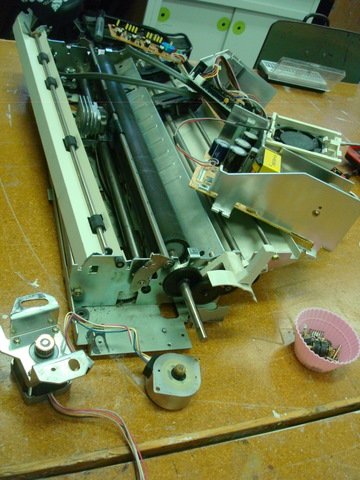
Also, I dissasembled a used ($3) EPSON LQ-1050 dot matrix printer , and was able to salvage 2 unipolar stepper motors and a plunger solenoid. These motors run at 35V, the carriage motor being a 4 phase 200 pole HB (Hybrid) stepper with a coil resistance of 10.5 Ohms per phase, and the paper feed motor being a 4 phase 48 pole PM (permanent magnet) stepper with a coil resistance of 79 Ohms per phase. The plunger solenoid has a coil resistance of 22 Ohms. As an added bonus, I can forsee recycling the stainless steel rods into guide rods for future equipment builds.
I was excited to see that I can use the salvaged unipolar stepper motors with the grbl shield used in the MTM SNAP assignment by simply wiring up 2 of the phases with 4 of the 6 wires. I simply used an ohm meter to determine the phases, and selected the wires pairs which gave the lowest ohm reading.