SUMMARY
The program, hello.bus.45.c, was modified in 2 areas to achieve the result of blinking an LED when a particular keyboard character was depressed. In line 41 of the code, there is defined a node_id, which was assigned 0 for the bus, and 1, 2 and 3 for the three node boards. In addition, on line 217 the flash() function was commented out. Otherwise, the LED lit up whenever any key was depressed! By commenting out this line, the LED was activated only when the assigned key was depressed.
It took an embarrasing amount of time to figure all this out, but better late than never, and 1.5 hours before Wednesday's lecture too!
We also got a start on working on our radio board. This looks to be an interesting project, with the added challenge of soldering unbelievable small parts on a circuit board. The components are between 1 and 2 mm in dimension, essentially a very coarse grained sand. The traces to the microprocessors are about 1 mm apart.
UPDATE
After lecture, we noticed that although the individual LED's would light up when keys were depressed, we did not always receive a character response in the python program TKinter interface. I was not getting a screen echo with board node No. 1, and Mercedes had a similar problem with all of her boards (or even worse, just getting a string of garbage). It turned out that a problem with one node board could knock out the whole string of lights! We needed to clean up a few solder joints to get everything to echo back to the screen.
Programming the boards:
sudo make -f hello.bus.45.bridge.make
sudo make -f hello.bus.45.node.make program-usbtiny
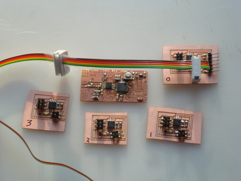
Just 2 board types used in this weeks assignment - one "bus" board, and as many "node" boards as we cared to mill and stuff. To view the output, we used the following python program term.py:
python term.py /dev/ttyUSB0 9600
Which would echo back to the screen the particular node board ID we had programmed, as well as flash an LED on the particular node board itself. In this example, there is one "bus" board, and three "node" boards, identified as node_1, node_2 and node_3. Depressing "0" lit up the bus, and 1, 2 or 3 lit up the respective node boards.
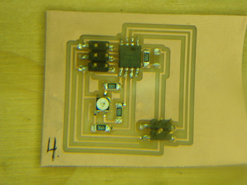
To make things a little more interesting, I made a fourth node board, replacing the LED with a RGB LED by modifying the .cad file. I used the code from the Output class (hello.RGB.45.c) in appropriate parts of the hello.bus.45.node.c to get the RGB to change colors. Each node board has to be programmed separately, and given a unique node ID, and presumably could be performing other tasks (like running a motor or controlling a speaker).
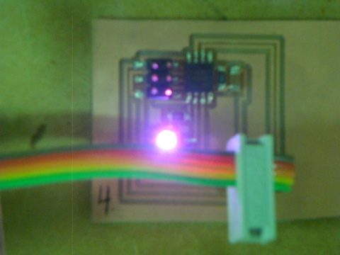
Getting a feel for how this works with the RGB LED illustrates how one could create a number of unique boards to perform discrete tasks, and then string them together with a ribbon cable on a network to control inputs and outputs so as to accomplish a more complex series of actions.