SUMMARY
Reflection on the final project presented last June has yielded the following results:
1) The rotating table turned too fast, and
2) The foam cutting tool was too cool
To solve the first problem, it became apparent that the motor control for the rotating table would need to operate independent of the three axis control as implemented with the GRBL shield and Arduino as used in the MTM SNAP. A 50-1 geared down DC motor in the fab lab inventory may serve this pupose well, as controlled through a modified board from the Output class.
To solve the second problem, I constructed a nichrome wire cutting tool (pictured right) using 1/4" plywood on the laser cutter, and a variable transformer to output the voltage between 5 and 12 volts. This approach needs further refinement, as it is not easy to create a tool with a point out of a soft wire.
Furthermore, I will probably reconfigure the machine to operate more as a lathe with the work spinning on a horizontal as opposed to vertical axis. I anticipate then being able to use one motor to drive 2 tools (for simultaneous cutting on the inner and outer surfaces), although it has yet to be seen how well this will work.
Thus, CCTM very much remains a work in progress, though not in limbo.
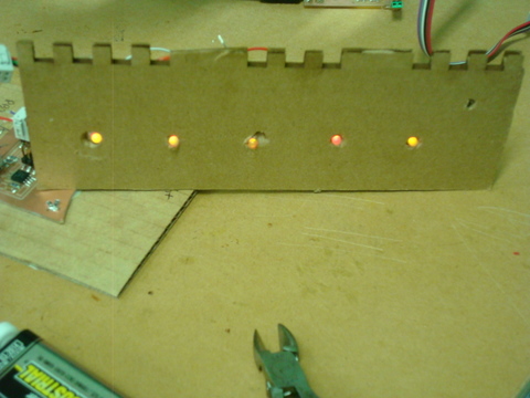
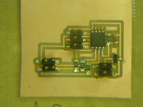
Mary K and I collaborated on her final project, I assisted in designing and modifying the needed LED circuitry for a blinking (twinkling) star, with generous technical support from Mercedes. We used the blinky board from the Output class, and modified the CAD file to replace the surface mounted RGB with a 4 pin header to which a full size RBG was attached.
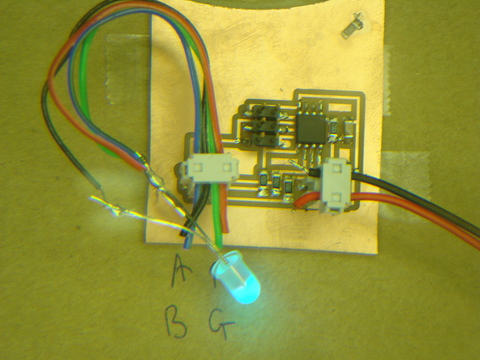
Interestingly, when we took some RG LED's out of the fab lab inventory, we found that we could not get the board to flash between Red and Green. It turns out that not all LED's are created equal, and the 4 pin configuration we wired up wasn't working with the anode wired to the voltage.
The solution was to no longer have the 4 pin header source current, but to sink it, so we cut the power to the anode pin and turned it into a ground (note the blue wire), as the following picture illustrates:
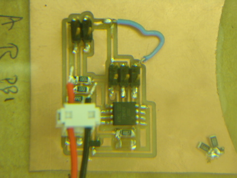
Which then ran the 5 LED array just fine. You can see the finished result in Mary K's final project.