SUMMARY
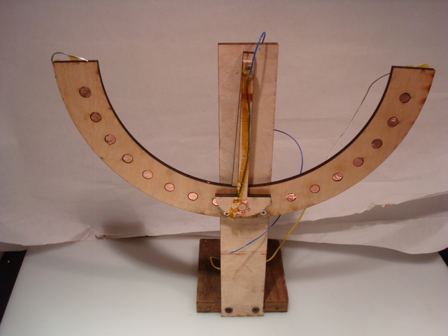
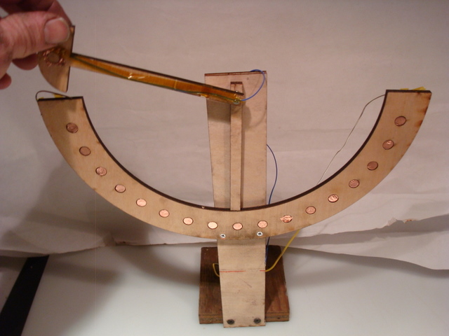
I built a pendulum and detector array, in hopes of measuring discrete signals received during the period of the swing using the "step effect" board. My idea was to have 17 detectors at 10 degree phasing respond when the pendulum swung past, and see if I could measure the rate of change from point to point as a function of time. I cut small circular plugs out of 1/4 inch plywood, and reinserted with a copper foil in hopes of measuring a charge and discharge of a crude air capacitor as the pendulum, with its own copper foil plug, swung past and completed the circuit. Unfortunately, this seemed to be doomed to failure, as 1) the "capacitors" on the detector side were all hooked to one common wire, so the 17 discrete "plates" acted as one, and 2) the copper foil followed the shape of the contour of the plug, and created a 3 dimensional shield profile with a solder joint on the back, which is not really a capacitor at all. Needless to say, I received no meaningful output from this experiment.
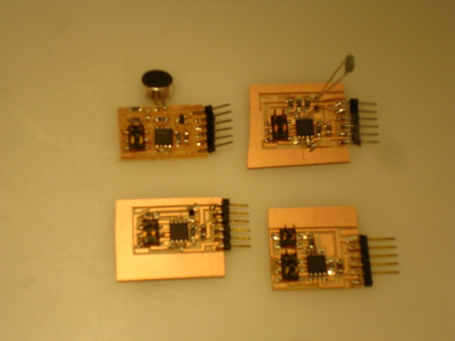
On a positive note, I did get three out of four boards to actually work, and once I discover the short on my sound board, should be able to experiment with that as well. The python program with Tkinter provided a meaningful graphical output to the computer screen.
DISCUSSION
Although the initial implementation was a failure, my next step would be to make the capacitor array properly (without a thickness). Also, I need to compensate for the fact that I have a plate mismatch, as normally an air capacitor would have an equal number of plates on either side of a dielectric to hold a charge. Furthurmore, I am beginning to doubt if this particular approach will yield any measurable differences at all, and may resort to detecting the rate of change of the pendulum swing using a different technique altogether.
One possibility would be to use the light board mounted to the pendulum, which would detect the 17 holes as "bright" when it swung past. On the detector side, I would replace the 17 plugs with a LED array. That might actually work!
July Update
To program the boards once they are made:
First, run the provided .make file to compile the C program, which yield your .hex file with the following command:
sudo make -f hello.XXXX.45.make
All of the boards this week used the AVRtiny45, and "XXXX" refers to the input board you are using (for example, "temp" as in hello.temp.45.make)
You may then flash the microcontroller using avrdude in the terminal window, while in the directory in which the .hex file resides using the fabISP and ribbon cable connector connected to the 6 pin header on your target board:
avrdude -p t45 -c usbtiny -U flash:w:hello.XXXX.45.c.hex
Alternatively, you can flash the microprocessor with the given .make file:
sudo make -f hello.XXXX.45.make program-usbtiny
Hook up the FTDI cable to the board, and output to the computer using a serial interface in one of two ways:
Serial communication via command window: type this in your command line
python rx.py /dev/ttyUSB0 9600
where ttyUSB- is your FTDI port. To find out what port is being used, plug in your FTDI cable and on your command line type:
ls /dev/tty*
typically in Ubuntu, it will be /dev/ttyUSB0, but modify as needed
Serial communication with GUI Python Ttinker: type this in the command line:
python hello.XXXX.45.py /dev/ttyUSB0
Note that you do not want to append the baud rate. A GUI interface will display the output in bar graph form in this example