I reviewed lecture six from the archive beginning at about minute 49-1/2, and was able to discern the following as to how to place a resistor in the schematic:
R2 = R_1206('R2'); #identifying the part and its footprint
pcb = R2.add(pcb,XTAL1.x,J1.y,z,angle=90) #adding resistor R2 to the schematic with reference to existing parts on the board
then defining traces to wire it in with:
pcb = wire(pcb,w,IC1.pad[5],R2.pad[2]) #pad 5 of the attiny connects to pad 2 of the resistor
pcb = wire(pcb,w,J1.pad[6],R2.pad[1]) #pad 6 of the 2x3 jumper connects to pad 1 of the resistor
In his hardware description, Neil placed the resistor with respect to existing parts on the board (the J1 header and oscillator XTAL1). Also, as he had defined the size of x and y as x=1 and y=1, so I was also able to place the resistor with the following equivalent:
R2 = R_1206('R2');
pcb =R2.add(pcb,x+.15,y+.22,z,angle=90) #the origin 0,0 being lower left
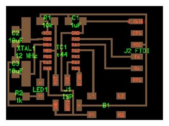
This gave me enough information to start fiddling with the descriptions myself. Our first task was to also get rid of the 20MHz crystal and replace it with a 12 MHz crystal, like the one we used a couple of weeks ago in the FabISP. Not because we wanted to, but we did not have the 20 MHz in inventory. But no problem, in the lengthy file provided to us there seems to reside definitions for many parts used in the history of the fab lab, like so many legacy lines of code in DNA. It was a simple matter to place the 12 MHz crystal with the following, which was modified from the FabISP.cad file:
XTAL1 = XTAL_CSM_7('XTAL1\n12 MHz')
pcb = XTAL1.add(pcb,x+.17,y+.58,z,angle=90)
and then also adding in a couple of capacitors with:
C2 = C_1206('C2\n18uF');
pcb = C2.add(pcb,XTAL1.pad[1].x-.09,XTAL1.y+.13,z,angle=90)
C3 = C_1206('C3\n18uF');
pcb = C3.add(pcb,XTAL1.pad[1].x-.09,XTAL1.y-.13,z,angle=90)
I then added a blue LED and resistor to pin 6 of the attiny:
LED1 = LED_1206('LED1');
pcb = LED1.add(pcb,XTAL1.x+.12,J1.y+.03,z,angle=-90)#put LED on the board
R2 = R_1206('R2\n1k');
pcb = R2.add(pcb,LED1.x-.18,LED1.y-.06,z)#put resistor on board
and then wired it in:
pcb = wire(pcb,w,R2.pad[2],LED1.pad[2])#grounded resistor to LED
pcb = wire (pcb,w,LED1.pad[1],
point(IC1.x-.18,LED1.y+.24,z),
IC1.pad[6])#wired to attiny
I also put in a button, and wired it in:
B1 = button_6mm('B1')#gave it a name
pcb = B1.add(pcb,J1.x+.33,J1.y-.105,z)#put it on the board
pcb = wire(pcb,w,B1.pad[2],J1.pad[6])#wired to ground pin
pcb = wire (pcb,w,B1.pad[1],
point(IC1.x+.27,B1.y+.47,z),
IC1.pad[11])#wired to attiny
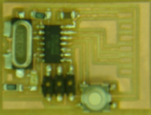
I had to widen the board to accommodate the button. In hindsight, I should have shrunk it down again to acheive a smaller board. Still need to solder in the pins for the FTDI cable so we can program next week.