COMPUTER CONTROLLED TURNING MACHINE
FINAL PROJECT PROPOSAL - UPDATE
General
This semester's fab academy has provided the needed background understanding to proceed with the project more or less as described at the beginning of the year, with a few reservations. Last January, the description was based upon what I wanted a machine to do - now it will be constructed with my new understanding of what a CNC machine actually can do. Our project to build the MTM Snap, using an arduino and stepper board shield with Grbl in the Processing programming environment running in the Ubuntu Lucid platform has direct application to my final project goals.
Previous Work
Hadley Brooks has a link to his thesis titled "Plastic Foam Cutting Mechanics for Rapid Prototyping and Manufacturing Purposes (2009)". In it, he has a review of the history of foam cutting technologies.
Materials & Components
The BOM will not be substantially different from the MTM Snap. In addition, it will have hot wire cutters to carve the foam on a rotating stage. Tool mounts will permit the substitution of hot wire cutters with die grinder cutting tools.
Cost
The anticipated cost will be less than $500
Parts and Systems
The project is very similar to the MTM Snap, with the added dimension of a rotating platform upon which a block of styrofoam is carved. Rotation will occur along the z axis, tooling will move in x and z to carve an inner and outer profile such that a shell volume results. As we learned building the MTM Snap, one can flash an arduino with Grbl and interface with a stepper shield to control 3 DC motors. This project will require 2 such systems, one to carve the outer surface, and one to carve the inner surface. The 2 aruino systems will need to communicate so that the thickness of the shell can be accurately formed.
Processes
The work flow will be to take a cubic foot block of styrofoam, and attach to the rotating stage with 2 sided tape. As the stage rotates, the system which carves the outer surface with a hot wire will rough trim the workpiece along the z axis of rotation, from the bottom to top. The second system will then rough trim the inner volume, also from the base to the top of the workpiece. The purpose of the rough trimming will be to center the material on the rotating stage, much as a potter centers a lump of clay prior to raising a cylinder.
The 2 arduino systems will then be synchronized, and in tandem move up the z axis while maintaining the desired Xinner and Xouter to carve the desired shell thickness.
Tasks to Complete
We are still having issues with the MTM Snap and associated systems, and need to solve those issues prior to integrating into this project. In addition, I need to see how to coordinate the 2 arduino systems to they cut the desired shell volume accurately.
Schedule
The prototype system is estimated to be completed in mid July, 2011
Evaluation
The success of the project will be measured by the actual output of a styrofoam pattern, which will be invested in green foundry sand, and displacement cast with a copper alloy bell metal
SUMMARY:
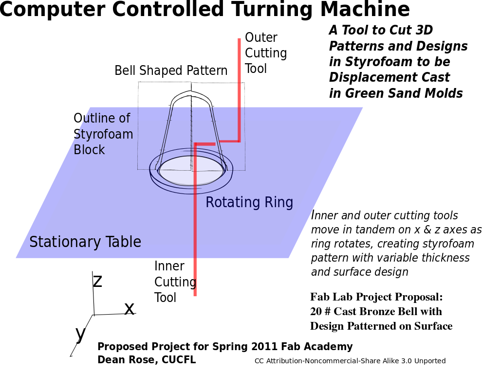
Design and build an open source computer controlled turning machine which rapidly shapes three dimensional volumes in polystyrene. A one cubic foot block of foam is attached to a rotating ring, with the inner and outer surfaces shaped with opposing tools as they move upwards in tandem on the z axis (see project schematic). The process may be thought of as being somewhat similar to that of a pottery wheel, where the tools involved in forming a volume are the thumb and forefinger. In this case, the outer tool will function as a lathe as it is moved in x and z, and the inner tool will function as a boring bar as it moves in tandem to create a shell volume of a variable thickness. Once the inner and outer surfaces have been described, the outer tool will then incise a design on the surface of the volume in x and z as the ring is precisely rotated in tandem and in discrete increments.

PURPOSE:
Styrofoam volumes may be invested in foundry green sand, a plaster and sand mix, or by ceramic shell. Once invested in a suitable and available medium, the stryrofoam will be displaced by a molten metal such as aluminum, copper alloy, or cast iron. So long as the volume is continuous, and the work is properly gated, an accurate copy of the foam pattern results. The advantage of displacemnet casting over other methods is that patterns do not have to be withdrawn (as in sand casting) or burned out (as in cire perdue), which allows for complex surfaces with undercuts to be fabricated and cast. A machine which would quickly, accurately and economically produce patterns which then could be fed into a minifoundry, would make personal fabrication of small production runs realistic.
GOALS:
The construction of the Computer Controlled Turning Machine (CCTM) will be accomplished by making use of recyled materials as available, and open source software and hardware. What is not locally available will be created at a fab lab, and any useful results made available under a Creative Commons license (Attribution-NonCommercial-ShareAlike CC BY-NC-SA). Thus, it would be a machine that could be constructed almost anywhere to produce durable and tangible items for a wide variety of applications. Furthermore, it should be intuitively designed so one may focus on the work and not the tool used to produce it.
FAB LAB SPRING 2011 PROJECT PROPOSAL
In addition to the CCTM, a 20 pound bell cast in copper alloy, with a raised pattern design on surface.