SUMMARY
CONSTRUCTION
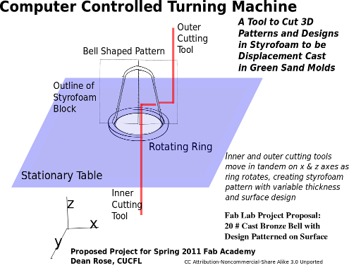
A sturdy table was constructed from a 12" x 36" sheet of 1/8 inch steel, supported by 4 legs to a height of 16 inches. A 6 inch hole was cut through the table, over which the rotating stage rests.
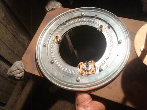
Rotation of the stage is accomplished with a 1/4 inch thick laser cut acrylic ring with a 12 inch OD and an 8 inch ID. The inner ring ID has a gear profile incised, in this case with 64 teeth. A motor with a 1 - 1/4 inch gear with 8 teeth drives the rotating stage, and 2 similar gears at 120 degree phasing act as idlers to keep the rotation true in the X-Y plane.
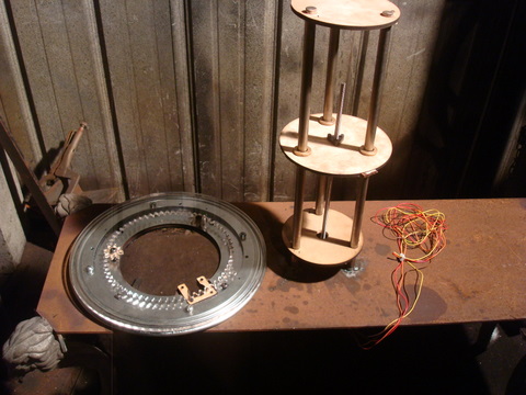
A tool post constructed from three 1/2 inch stainless steel rods at 120 degree phasing is used to raise a table upon which a styrofoam cutting tool is mounted. The Z table is a laser cut 1/4 inch piece of plywood 6 inches in diameter with three 3/4 inch holes cut at 120 degree phasing through which 1/2 inch bronze bearings are inserted. The bearings are secured to the plywood with hose clamps. A stepper motor raises and lowers this table vertically.
A tool driver is similarly constructed to hold the styrofoam cutting tool, though smaller and lighter. Three 1/4 inch stainless steel rods at 120 degree phasing are used to drive the cutting tool with three 3 inch laser cut plywood disks, acting something like a syringe being driven horizontally by a stepper motor. Quarter inch bronze bearings were used.
Here is a shot of the rotating stage
And a shot of the Z tool post which will carry the tooling
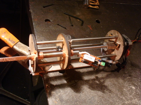
A rough assembly
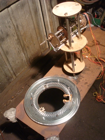
A close up of the tool shuttle. I have a styrofoam hot iron inserted. Only about 3 inches to move in and out.
MATERIALS
Much of the project is repurposed from the MTM Snap. Stainless steel rod was scavenged from my scrap pile. Bronze bearings were secured from a farm supply store, and miscellaneous fasteners and additional parts from a host of "big box" hardware chains.
COST
The total cost to assemble this project is approximately $350, broken down as follows:
The costs for the electronics for the grbl shield has been outlined by Ward, as has the elements of the MTM Snap. The total of repurposed materials for this project is $150.00
An arduino Uno to drive the grbl shield is valued at $30
Acrylic, Stainless steel rod and miscellaneous fasteners added another $120
A larger motor to drive the rotating stage, about $50. I used a variable speed drill in the testing phase, but need a more powerful stepper motor which can be computer controlled.
DISCUSSION
The principal thrust of the final project was to assemble a working area using tools and techniques studied during the Spring 2011 Fab Academy. The basic structure of the machine was cut and assembled in a job shop. The fab lab provided the laser cut templates, which permitted a level of precision beyond the ability of hand fabrication. These plywood templates were used for the registration of the translating elements of the machine - 1) to raise and lower a table vertically carrying a foam cutting tool which 2) moved horizontally into and out of the work.
The grbl shield works well for small translations. However, I have
found that if one depresses the arrow cursor keys too often, it will
crash the software. It is best to go easy with the arrow keys, and
setting the step settings to .001 inch (option 2). Also, the Z table
occaisionally will struggle with the weight of the cutting tool when
moving vertically upwards, which can also lead to a system crash. The stepper motors from the MTM Snap were adequate for the tool post assembly, but not powerful enough to drive the rotating stage. I had to replace the drive mechanism with a more powerful motor. For the purpose of testing, I used a 3/8 inch variable speed drill. I also removed the lazy susan bearing, as it was has too much drag.
The drill did not permit slow enough rotation to test the cutting tool, so the short video shows the cutting tool simply slicing off a bit of foam using 2 of the stepper motors.
VIDEO
styrofoam cut from dean rose on Vimeo
Lazy Susan bearing design from dean rose on Vimeo
Rotating Stage from dean rose on Vimeo
FUTURE WORK
Much work remains to be done. A suitable drive motor needs to be identified for the rotating stage. Also, the tolerances on the bearings need to be improved. I reamed out the 1/4 inch bearings with an "F" bit, which worked well, but the 1/2 inch bearings were oversized with a 17/32 bit. This proved to be too large, but at the time I did not have a 33/64 bit which would have been more suitable.
The timeline for project completion is estimated to be mid July 2011.
I will also make the tool post so that it mounts on rails, as well as rotates. This will allow for more precise positioning of the cutting tools.
Once the machine is functioning as envisioned, the fab modules will be used to generate a g code file which will define a 2 dimensional profile which will be cut as the stage rotates. I will be able to either hand draw and scan this profile saving as a png, or generate an image by software description.
EVALUATION
The desired result will be a bell shaped shell volume carved in styrofoam, which will be displacement cast in green sand with a copper alloy bell metal. The first test will simply be to get the CCTM to create smooth inner and outer surfaces as defined by png files. The second test will be to incise a design on the surface of a styrofoam bell, also using g-code generated in the fab modules, and pouring a second bell.