Assignment: build a wired and/or wireless network with at least to
nodes.
I made the hello.bus (wired) and I'm continuing to make the hello.radio
(wireless).
Tools & techniques
- Hello.bus board & the hello.radio printed on the modela
- Host program: term.py
- Program for the hello.bus board: hello.bus.c and make.file
- Stuffing the boards by soldering
Result
Findings hello.bus
Connection with hello.bus board. When running the program on the
mac it doesn't
function so well as running the program on Linux computer. Iwouldlike tofind out whatitis,but I haveabit oftime
constraints.
Wireless network Iwouldvery much like
to make the
helloradio developed byBrianMayton,DavidCranor,RehmiPost.
We had nodouble-sidedPCBboard.So Ichose thealternativeway whichwas "the
top
traces could be milled from a single-sided PCB blank with a strip
of adhesive copper foil on the back to define the ground plane."
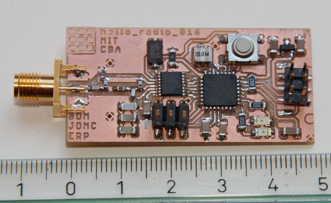
This is the result so far:
Findings hello.radio Istarted makingtheHello.radio.In the designthere are
also someviasin ordertotrace to
the
ground plane underneath the circuitry. Theseviascan be seen inthe outlineoftheradiohellopngfile.Whenthe outlinewillbe cut,
theseviaswouldbe drilled.Thishas not happened,becausethe diameter ofthemill
was toothickfor thesevias.It indicateswhy theCad.pysoftwarewas notrendering the vias.We've increasedthe diameter of
vias inthepngfile.Theproblemwasresolved.