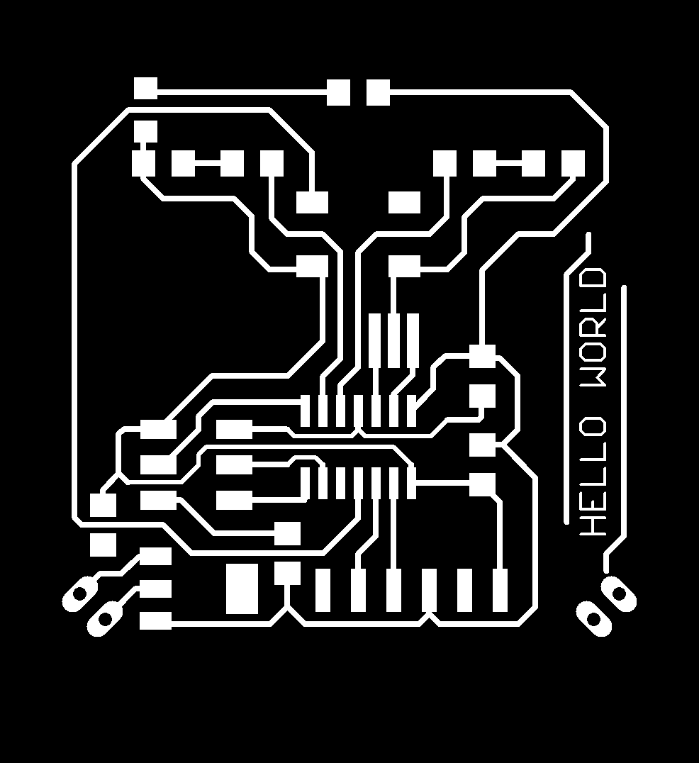
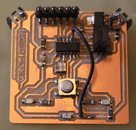
http://suchamagicworld.blogspot.com/2008/04/still-alive-heartbeat-irsensor-report.html


| // // // hello.light.44A.c // // photo transistor hello-world // 9600 baud FTDI interface // // Neil Gershenfeld // 10/27/10 // // (c) Massachusetts Institute of Technology 2010 // Permission granted for experimental and personal use; // license for commercial sale available from MIT. // #include <avr/io.h> #include <util/delay.h> #define output(directions,pin) (directions |= pin) // set port direction for output #define set(port,pin) (port |= pin) // set port pin #define clear(port,pin) (port &= (~pin)) // clear port pin #define pin_test(pins,pin) (pins & pin) // test for port pin #define bit_test(byte,bit) (byte & (1 << bit)) // test for bit set #define bit_delay_time 100 // bit delay for 9600 with overhead #define bit_delay() _delay_us(bit_delay_time) // RS232 bit delay #define half_bit_delay() _delay_us(bit_delay_time/2) // RS232 half bit delay #define char_delay() _delay_ms(10) // char delay #define serial_port PORTA #define serial_direction DDRA #define serial_pin_out (1 << PA1) void put_char(volatile unsigned char *port, unsigned char pin, char txchar) { // // send character in txchar on port pin // assumes line driver (inverts bits) // // start bit // clear(*port,pin); bit_delay(); // // unrolled loop to write data bits // if bit_test(txchar,0) set(*port,pin); else clear(*port,pin); bit_delay(); if bit_test(txchar,1) set(*port,pin); else clear(*port,pin); bit_delay(); if bit_test(txchar,2) set(*port,pin); else clear(*port,pin); bit_delay(); if bit_test(txchar,3) set(*port,pin); else clear(*port,pin); bit_delay(); if bit_test(txchar,4) set(*port,pin); else clear(*port,pin); bit_delay(); if bit_test(txchar,5) set(*port,pin); else clear(*port,pin); bit_delay(); if bit_test(txchar,6) set(*port,pin); else clear(*port,pin); bit_delay(); if bit_test(txchar,7) set(*port,pin); else clear(*port,pin); bit_delay(); // // stop bit // set(*port,pin); bit_delay(); // // char delay // bit_delay(); } int main(void) { // // main // static char chr; // // set clock divider to /1 // CLKPR = (1 << CLKPCE); CLKPR = (0 << CLKPS3) | (0 << CLKPS2) | (0 << CLKPS1) | (0 << CLKPS0); // // initialize output pins // set(serial_port, serial_pin_out); output(serial_direction, serial_pin_out); // // init A/D // ADMUX = (0 << REFS1) | (0 << REFS0) // Vcc ref | (0 << ADLAR) // right adjust | (0 << MUX3) | (0 << MUX2) | (1 << MUX1) | (1 << MUX0); // ADC3 ADCSRA = (1 << ADEN) // enable | (1 << ADPS1) | (1 << ADPS0); // prescaler /128 // // main loop // while (1) { // // send framing // put_char(&serial_port, serial_pin_out, 1); char_delay(); put_char(&serial_port, serial_pin_out, 2); char_delay(); put_char(&serial_port, serial_pin_out, 3); char_delay(); put_char(&serial_port, serial_pin_out, 4); char_delay(); // // initiate conversion // ADCSRA |= (1 << ADSC); // // wait for completion // while (ADCSRA & (1 << ADSC)) ; // // send result // chr = ADCL; put_char(&serial_port, serial_pin_out, chr); char_delay(); chr = ADCH; put_char(&serial_port, serial_pin_out, chr); char_delay(); } } |