Making a circuit board
Assignment
Make the FabISP in-circuit
programmer
Result
photos
Techniques/tools:
Roland modela with cad.py software (new software not installed)
Cutting out the traces: 1/64 bit
Cutting out the board: 1/32 bit
Solder iron temperature 75 x10 F
Tweezers
Magnifying glass with light
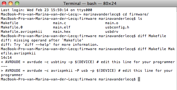
Programmer: AVRisp MKII
Software: AVRdude and cross Pack AVR
(both open source)
Materials:
png files: fabisp.png and fabispdim.png (archive)
double sided tape scotch 3M
FR1
Wire soldering lead/tin with flux, kester connection innovation
Findings:
Machining
When changing the end mill, I fastened the mill a little bit deeper
into
the head of the milling machine, pressed the view button. Then moved
the head above the middle of the FR1 plate. I pushed down to a certain
point. The mill didn't go any deeper anyway. So, I loosened the sews
of the head and put the end mill on the plate. Than fastened the screws
again and gave the order to the machine to mill the outline of the
plate to loosen the traced circuit board from the greater FR1 plate.
But the board came not entirely loose from the plate, while the
settings in the computer were correct. I think when zeroing mill, the
mill stopped from going down any further. Probably the head has reached
the minus Z endpoint and therefore stopped from going down deeper.
For resetting the modella, I didn't not turn of the machine as written
in the tutorial. I first pressed view and than at the same time
the up and down button. The light of the modela is winking.
Soldering
I find soldering a nice and relaxing job.
Downloading and adapting the
programs
I find it amazing how a microcontroller works and adapts to your
needs. Without any further mechanical action I can load a program on a
chip and make it do something. I find it magic, where command lines act
as spells. Now I have to learn the spells.
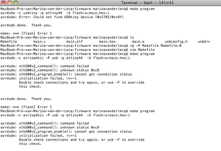
Connecting the Fabisp with
the working programmer
The
connection between the working programmer (AVRisp MKII) and my fabisp
didn't succeed the first time. The trouble was situated at R5 499.
Instead of soldering a resistor of 499x10^0 I placed a resistor of 499
x10^3. The resistance was too big therefore the current was too low and
I didn't got a signal on the USB interface. I desolder the component
and replaced it for the 499x10^.
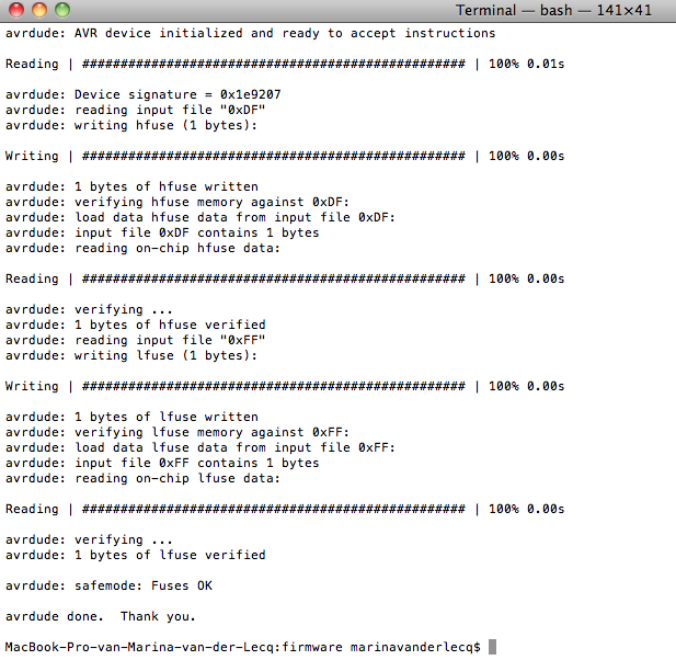
Programming the ATtiny44
After this conundrum of the connection was solved, programming the
ATtiny44 turned out succesfully.