Principles of the heart rate sensor with photo diode
and infraredlight LED:
The principle of measuring the heartbeat with a light source is based
on the transmitted and absorption characteristics of oxygenated and
de-oxygenated hemoglobin. Oxygenated hemoglobin absorbs more infrared
light and allows more red light to pass through while deoxygenated
hemoglobin absorbs more red light and allows more infrared
light to pass through. Red light is in the 600-750 nm wavelength light
band. Infrared light is in the 850-1000 nm wavelength light band.
Findings
- The first
version of the heart rate
sensor, I tested with the oscilloscoop with a light sensor
(...) and
an infrared light
(...)
(...)
showed signals. Unfortunately
it was not
my heartbeat. It had been just very exceptional as
it
would
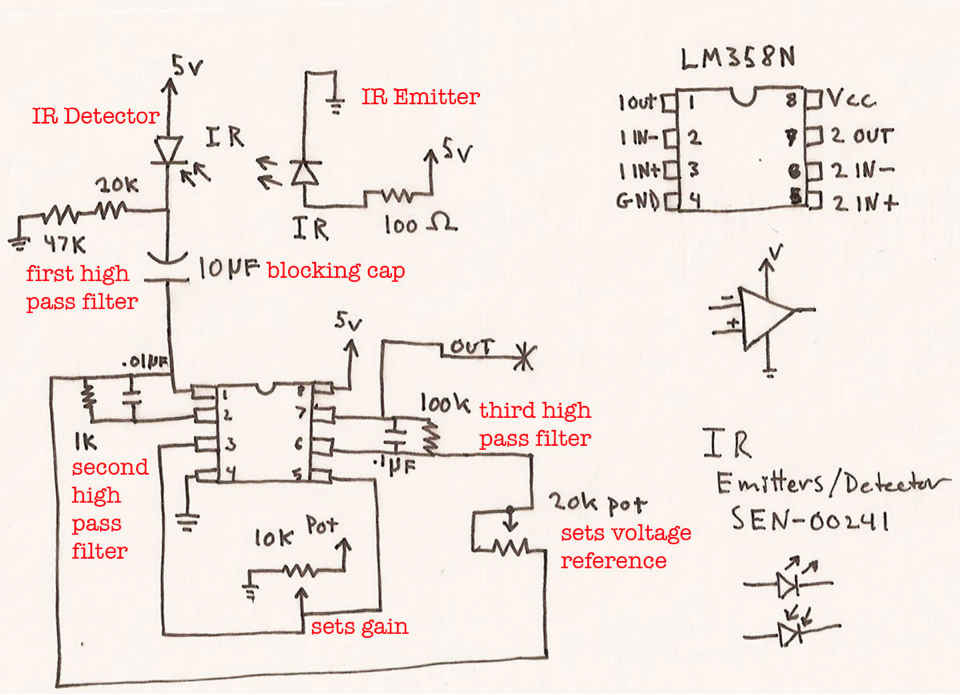
operate at once... I decided to add an amplifier, which should enhance
the signal. I decided to use the circuit previously
found on the internet, because in that
example,
an
amplifier was used.
This is the image of the circuit
and this is the link: http://www.johnhenryshammer.com/TEChREF/opAmps/opamps.html
I have used the eagle software to enter the design in order to mill it out on the MODELA later on. The pictures
below
shows the results of the eagle-software.
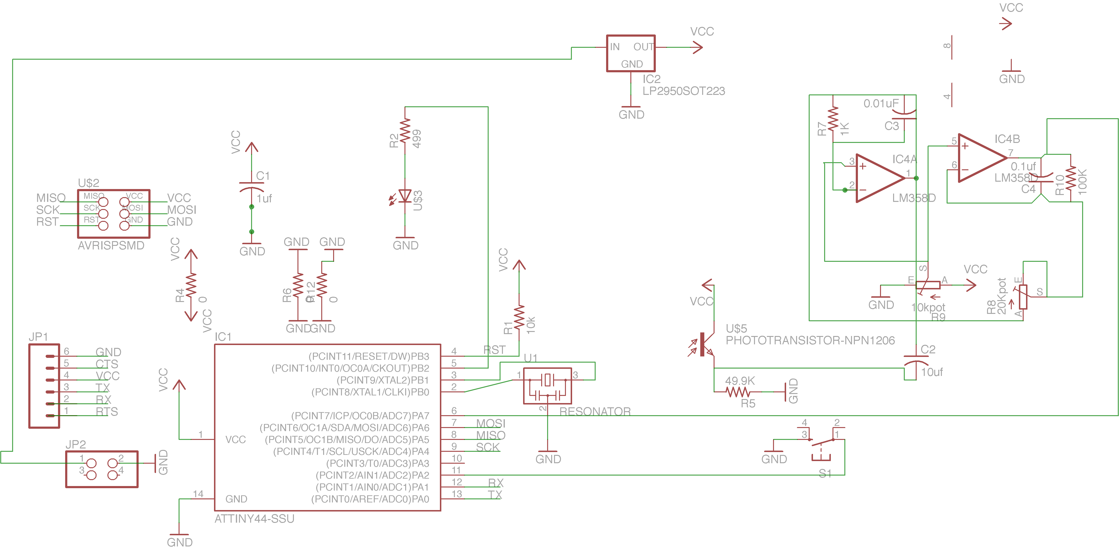
Schematic
layout
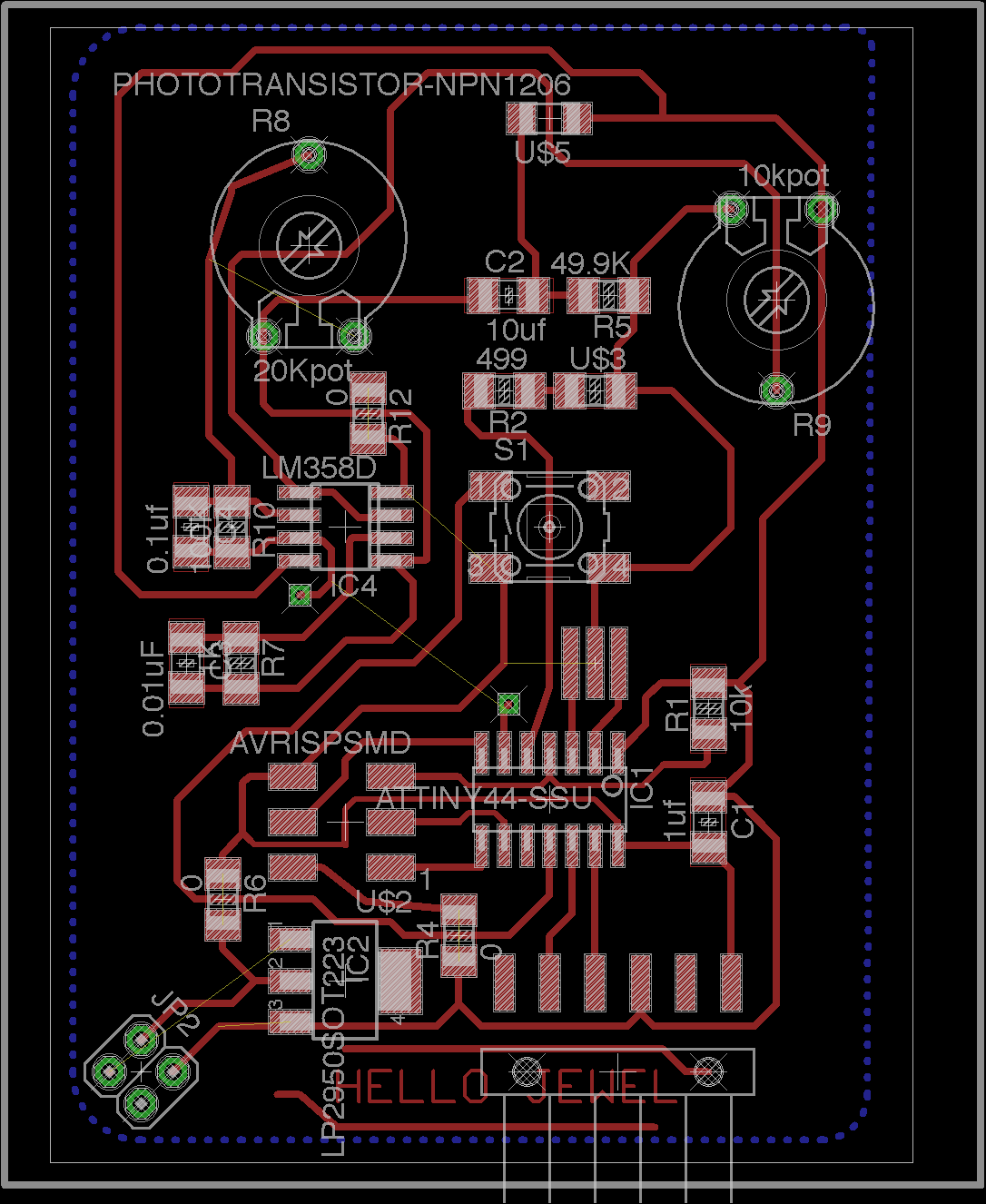
Board
layout
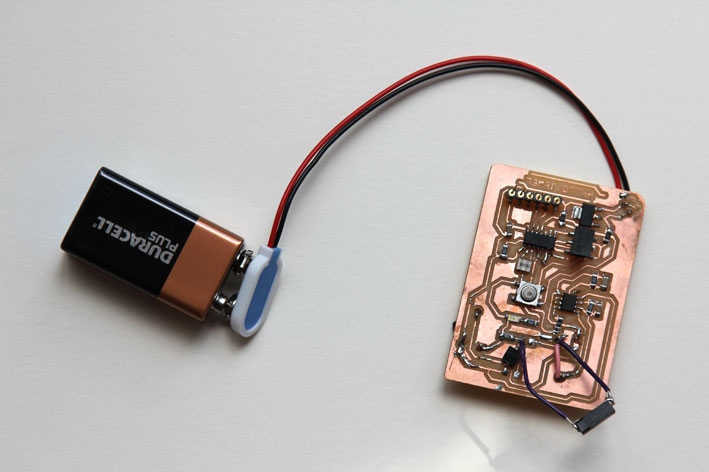
physical
board
At first
it did
nothing. I could not program the chip. Here came
debugging
into play.
1) I checked the soldered and the schematic again.
- The potential meter was connected wrong in the schematic
- I soldered the LM358 other way around. I learned more about
the different packages of the components.
- I think I used a wrong capacitor. I probably had misread.
Instead of 0.01 uF I used 0.1
uF
- At the end I found a missing trace of the voltage regulator. At first
I didn't
connect the board to the 9Volt battery, but
to the
external power supply to the header
to set the board to 5 volts. I
used a oscilloscope to measure its behaviour. Any
movement changed the signal, but
it was not my heartbeat.
Meanwhile
I had a
final
presentation of the fab academy. Time pressure... I wanted
to show something
closer
to what was my design. I decided
to make make
my design
physically. Sometimes
it's better
to start
all over
again. Moreover, you
can debug
better
with
separate
circuitry.
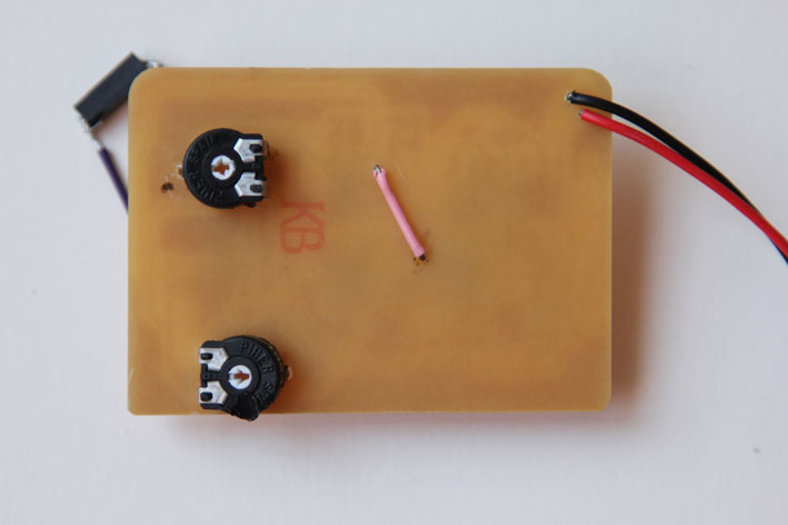
Below is the
result.
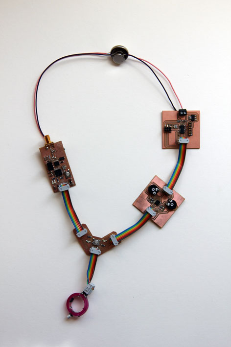
The circuit
I have
divided
into five parts: The chip, the amplifier, the LED, the sensor and
the 'hello
radio'.
The board
of the chip include
connections for the batteries, a voltage
regulator and an external
crystal
and some capacitors and resistors.
The board of the amplifier include two potentiometers and two high pass
filters.
The board of the LED include two LEDs and some resistors
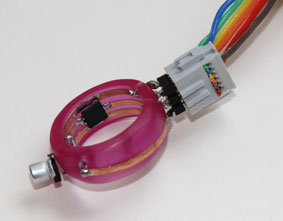
The circuit board
of the
sensor and the infraroodled
was made
in a ring. I believe the ring
would
imply
less
movement. I used copper foil and the vinyl cutter
to cut
out the circuit.
The
picture above shows copper
foil pasted in the ring and soldered
components.
This part of circuit include the first high pass filter.
Now debugging really came into play.
I learned more about active high pass filters. The reason ....
fout
ligt in de versterker. vermoedelijk is het filter
design niet
juist. high pass filter is anders aangesloten en gaat meteen van in
naar de out.
zie ontwerp
high frequency laat hoge frequenties door. een hartslag geeft ....
frequentie
optie:
digitaal filteren:
gebruik pin 13 om een potmeter op aan te sluiten die de functie krijgt
van als A REF (external voltage reference)
meet met de oscilloscope je hartslag en zet de weerstand van de
potmeter op het voltage wat je maximaal hebt gekregen met de
oscilloscope. zet in het programma AREF = 1voor de ATtiny 44
Vinyl cutting the traces in the
copperfoil
1) Open eagle PNG document in Illustrator and then choose live trace
and expand. You can still modify the traces a little. For example, I
made the lines a little thicker.
2) Choose print from the illustrator menu: place the object in the
lower left corner of the screen. Further operations of the vinyl cutter
on the device itself. The width of your file appears in the display.
3) Lift the handle at the back and slide the copper foil under the
wheels. The white marks indicate the possible position of the wheels.
3) Navigate through the menu Select roll. The force and speed I used
for copper foil 1cm = 60g / s
4) Click OK (PC) to print
Result
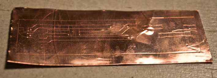
Copper foil fresh from the vinyl cutter.
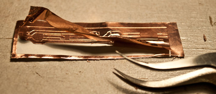
Carefully removing the residual material using tweezers.
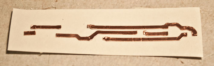
Ready to transfer the traces.....
![]()
with transfer foil.