This week's assignment make the MTMSnapmachine motion control.
Findings
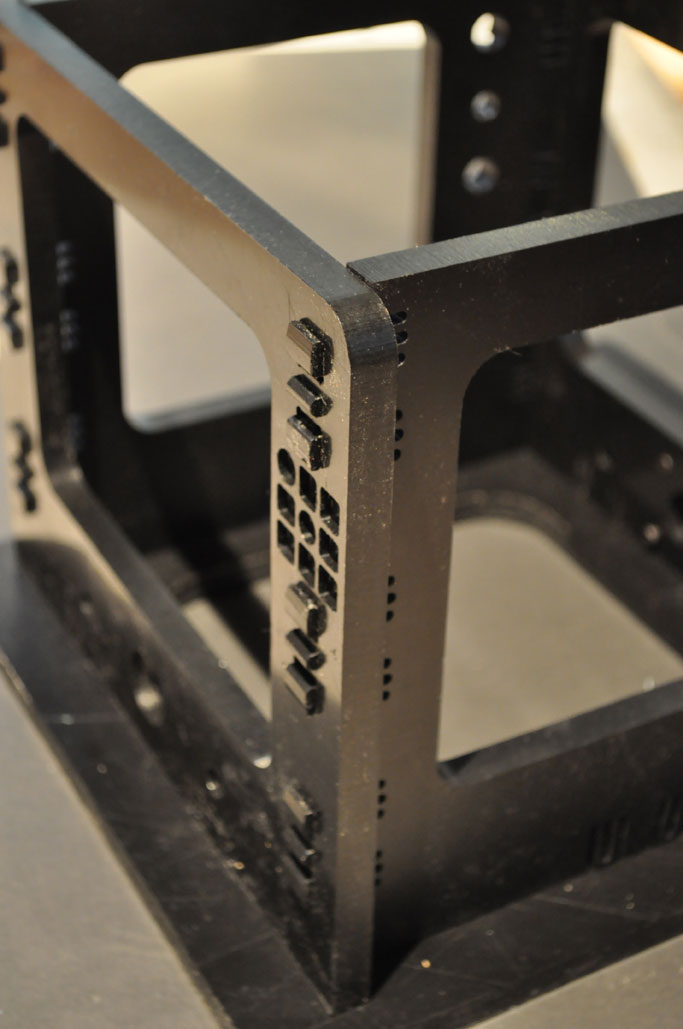
We first tested the press-fit joint. We found at one point
the joint is very tight; There's a little too much stress on the 'tenons'. At the other point the mortise is too loose. (see picture
below). You could see a fissure between the 'tenon and mortise' But
because of it's stress in the tenon it won't move.
File:
2 We scaled the drawing in Adobe Illustrator so that it fits to our board
(1200x600x12mm). We exported it to DXF-file. The Part Works-file
provided on the MTMsnap page pages has a different size than the
dxf-file so we couldn't use it. Therefore, we need to re-create the tool
paths with Pathworks, which was a good exercise.
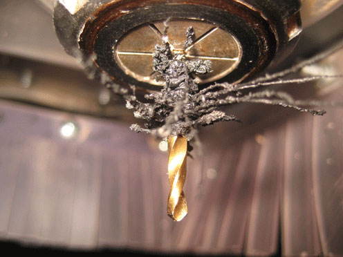
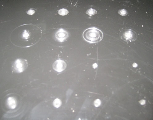
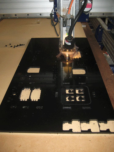
3 We had to stop the machine a several times to remove the melted
polyethylene rest material from the end mill. As you could see in the
picture below the rest material had scratched the surface while
drilling. Also it got too hot so the holes were slightly bigger at the
surface. We changed the plunge rate to 15.00, so the drill move
faster and the material wouldn't melt any more.
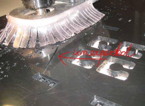
4 At one point we stopped the machine and when it resumed it cut the
surface, which it didn't suppose to do (see picture). Probably the
z-reference point was changes when we stopped the mill.
5 In the beginning the little cut-out pieces were sucked in the dust
extractor which make a hell of a noise which is not good for the
ventilator propeller.
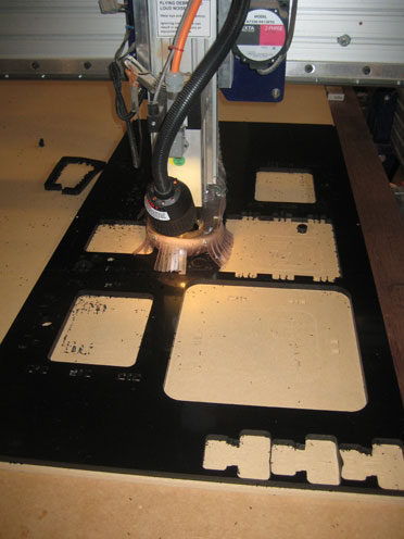
6 On certain places the edges are rough probably because of the
double-sided tape; the glue of the tape caused the cutting edges of the
end mill dirty because of which it didn't cut well. On places were no
tape was used the cutting outlines were fine until the final cut
loosened the inner part. It made a little burr.
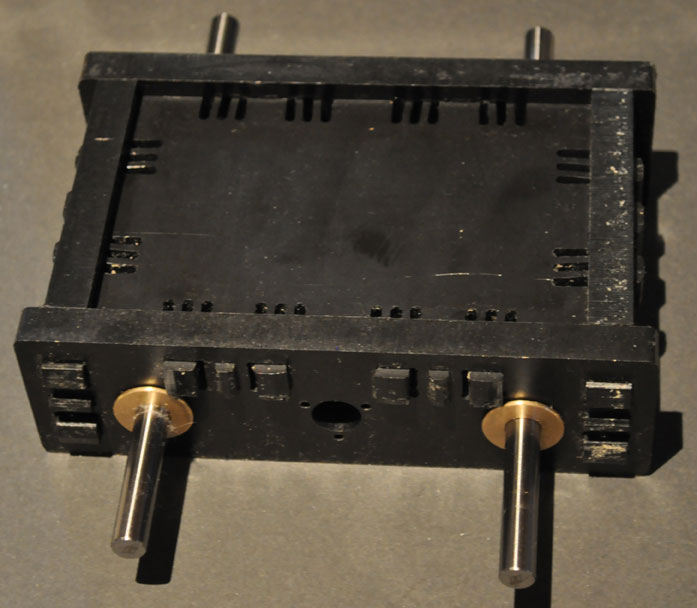
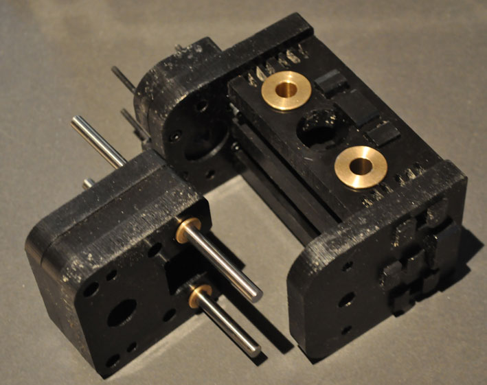
Assembly
Findings
- Partwork-file missed some holes. These we had to re-draw.
- We missed a few items, probably the jaw coupling and lead a crew. So we
can not continue assembling the mechanical parts.
- Assembling was not easy because ...?
Software
Materials & Techniques
- arduino duemilanove
- stepper motor Nema
- three separate stepper drivers designed by Jonathan Ward milled
on FR1-board with modella and soldered with components
- user interface program on the computer: gctrl designed/ inspired by
David Mellis
- program for Arduino board: grbl designed/ inspired by David Mellis
Findings
We first installed the following programs:
- arduino environment (in the end we didn't really use this)
- processing:
- we installed directly the program (grbl) from a github repository. https://github.com/damellis/grbl
- the gctrl-program we downloaded from another github repository on
: https://github.com/damellis/gctrl
Result
We programmed the arduino and tested the stepper drivers and motors.
These all functioned, but not at full speed.
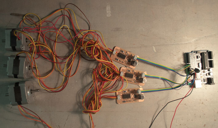
Electronics
We made the three small stepper boards, and tested them. During test
one
power supply blew up (in The Netherlands we use 220 V, while the power
supply from MIT was set to 110V). Later with new power supply (with the
same specs as the blown-up power supply) we tested the boards again,
and they
worked for a while. We tested the boards one by one. After disconnecting
the stepper motor and
connecting it to another stepper board, they don't work anymore. We
found out that there's an order in connecting and disconnecting. The
correct order to connect: first the motor to the stepper driver, then
the stepper driver to the power supply; and to disconnect: first the power
supply to the stepper driver, then stepper driver to the motor. We
made two new small boards that still work after multiple test.
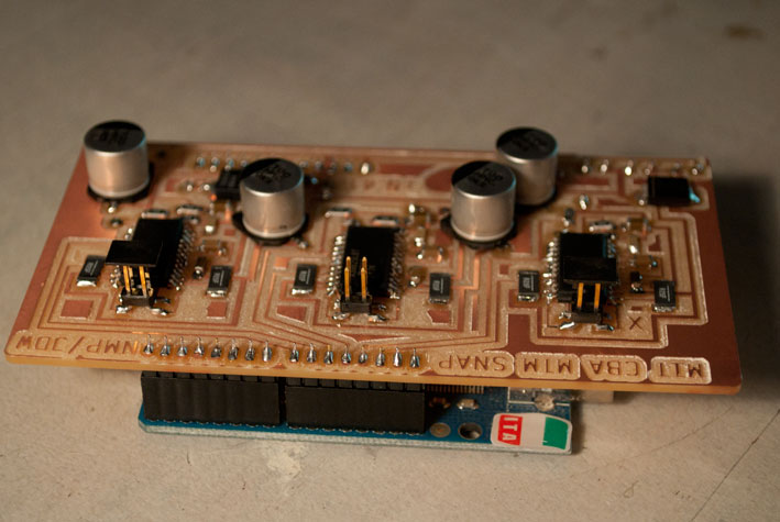
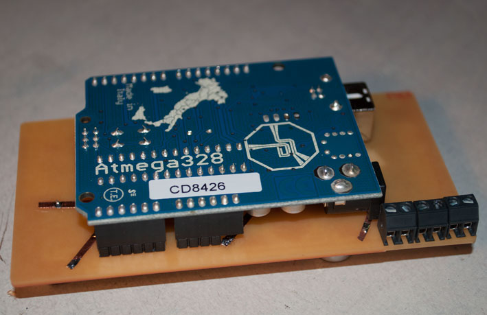
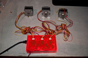
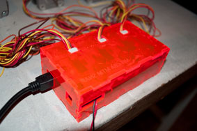
Meanwhile we decided to make the Arduino shield with all 3
stepper drivers, because it is much easier to make a box for both the
arduino and the arduino shield than one box that must contain the three small
boards. The arduino shield on top the arduino is less fragile and
you need less wires. In the
first test, by giving 5V to all step lines (X, Y, Z) only X stepper
motor
works. We measured the different traces of the X,Y and Z drivers with a
multimeter. We found out that the step pin of the X stepper
driver is
a
pull-down line. That means when the pin is disconnected, it gives 0 V.
The step
pins of Y and Z stepper drivers are pull-up lines (when disconnecting
the pins,
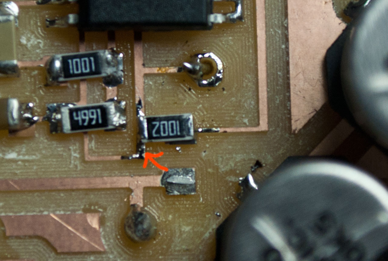
they give 5 V). So we re-arranged the 10k resistor of the X stepper
driver, to make it pull-up line, like the other stepper drivers (Y and
Z).
Results
Changing the resistor
When we tested the Arduino shield, connected to Arduino board, we found
another problem when we tried to move the stepper motors. They made
some movement but couldn't rotate. We got help from Bas Withagen from Fablab
Amsterdam. He suggested that the stepper motor was not connected
correctly to the stepper driver. So he changed the order of the stepper
motor's wires, and this time it could rotate, but not perfectly. He
said that one pair of wires could be switched wrongly. We changed again
the brown wire and the red wire. Now it could rotate as it should.
Wires of the stepper motor are connected wrong
Wires of the stepper motor are connected right
Ideas for improvement
- optical encoders for the stepper motors and spindle
- spindle control (so we can turn the spindle off and on with the
program)
- emergency hard switch to cut electricity from the power supply (it would be
faster to press than to pull-off the plug from the power outlet)
- soft switch that connected to Arduino so we can stop all stepper
motors and spindle in case something goes wrong (and we still want to
control the stepper motors afterwards)
- spindle speed control so we can adjust the speed for different
materials
- Z automatic positioning combined with a sort holder for the endmill,
so we can determine the exact Z origin without manually adjust the Z
position (similar idea like auto focus in laser cutter)