9. Input Devices
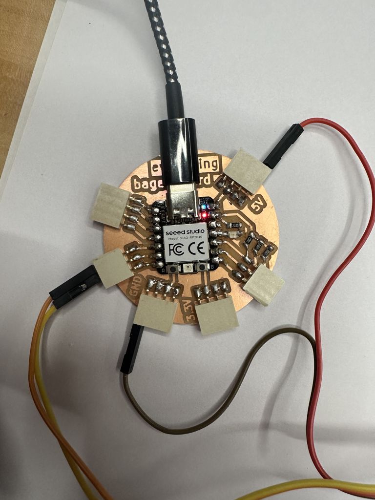
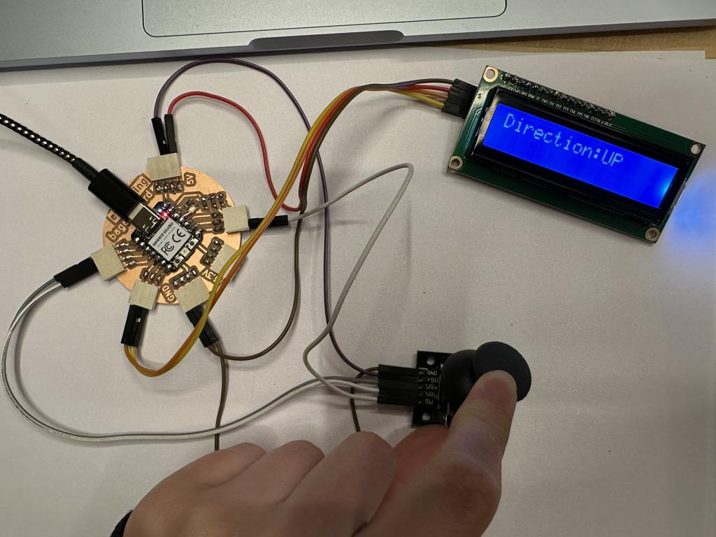
This week I used my custom-made circuit board from Electronics Design Week to power an LCD screen controlled by a joystick.
Research
I had done some of this work before in a previous fabrication course, but I wanted to familiarize myself with using these technologies again—especially learning how to use a joystick. I already understood the function of my board, so my biggest challenge this week was figuring out the wiring and how to actually make my board power something and be useful.
Materials
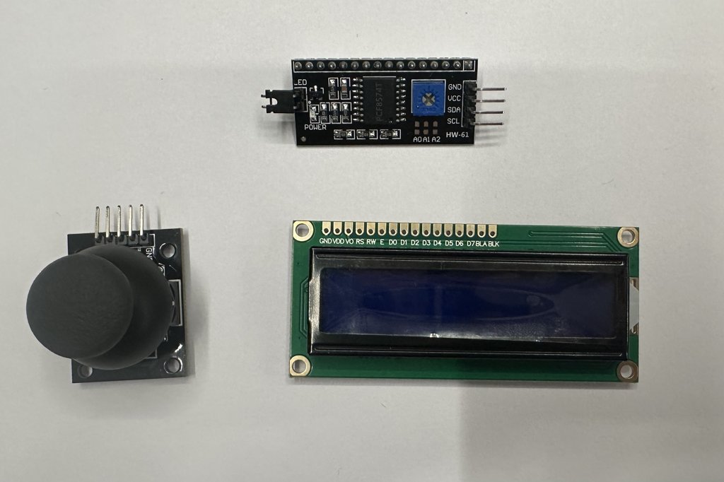
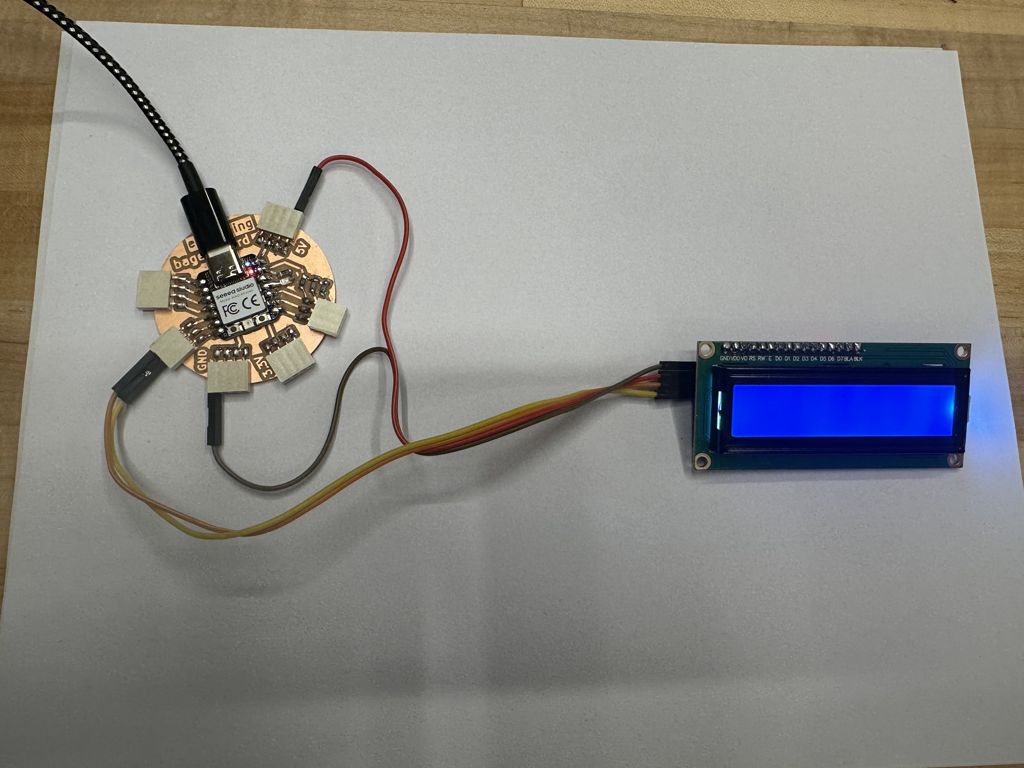
The first step I took was gathering my materials: an LCD screen, an LCD backpack, a joystick, and nine female-to-male wires. I used breadboard wires to dry-fit the components and test how they would connect to my board, and I thought the setup looked great!
Setting up LCD Screen
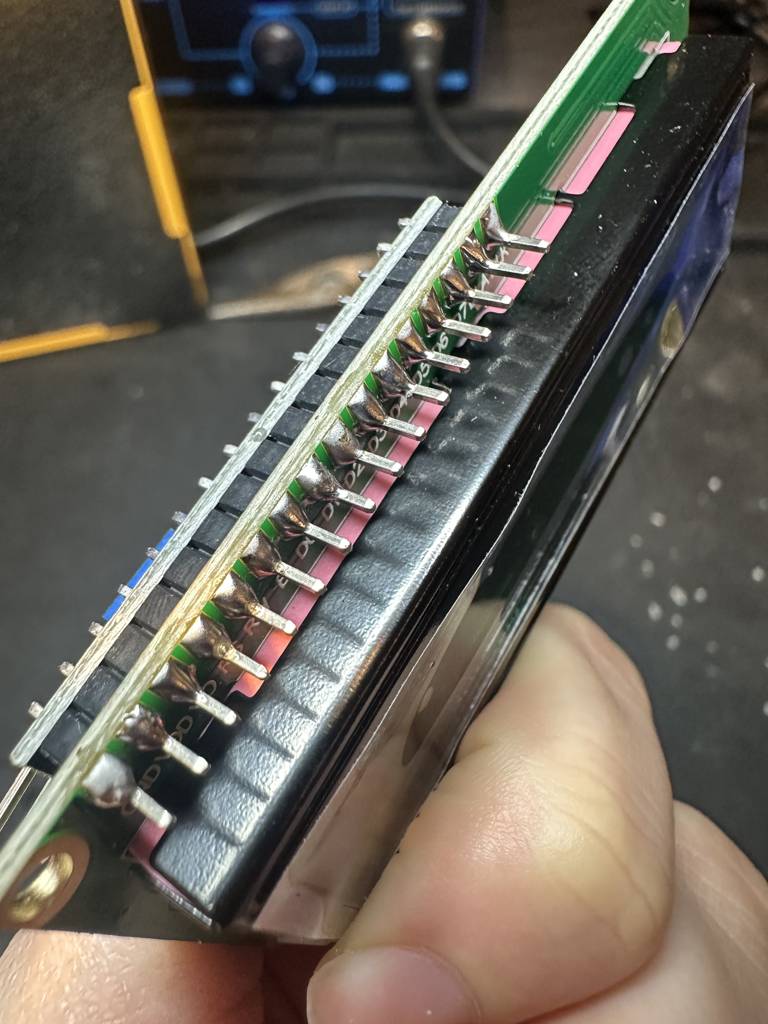
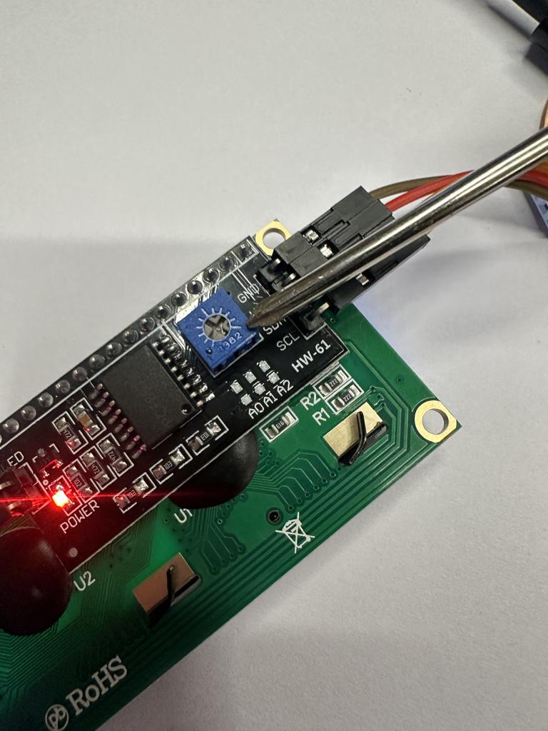
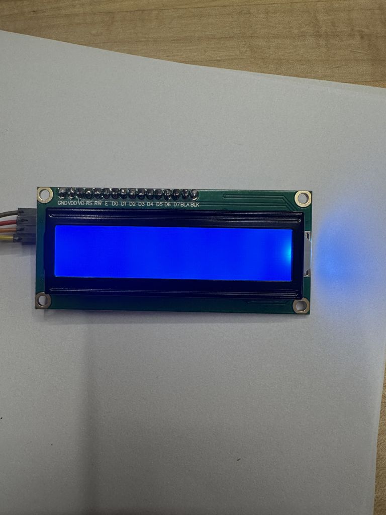
The first major task was soldering the LCD backpack onto the LCD screen. The screen has what feels like a million pins, and soldering each one directly to the board would be inefficient. When I had used an LCD before with an Arduino, it took up nearly all the pins—and my board doesn’t even have that many. The LCD backpack simplifies this by soldering to all 16 LCD pins and converting them into just four: GND, VCC (power), SDA, and SCL. SDA and SCL are used for communication between the screen and the board.
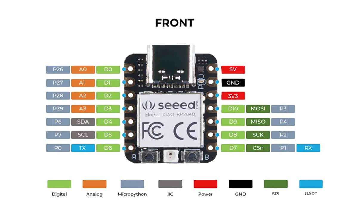
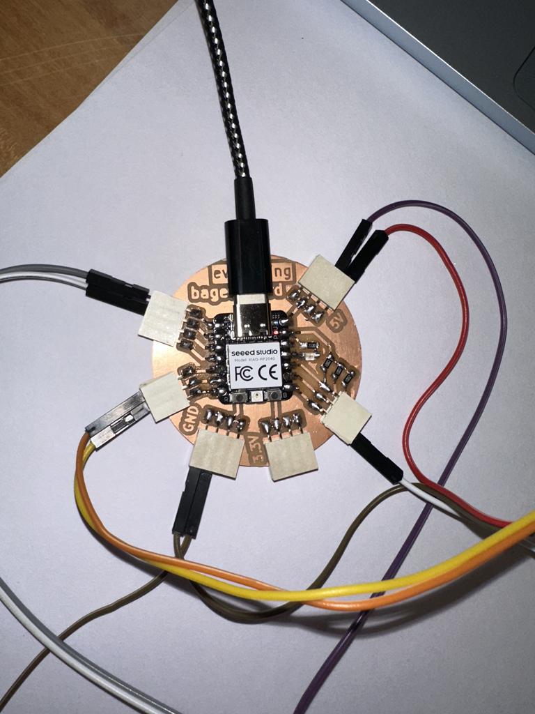
Once I connected the screen, I ran wires from ground to ground, power to power, and plugged SDA and SCL into their corresponding ports on the board.
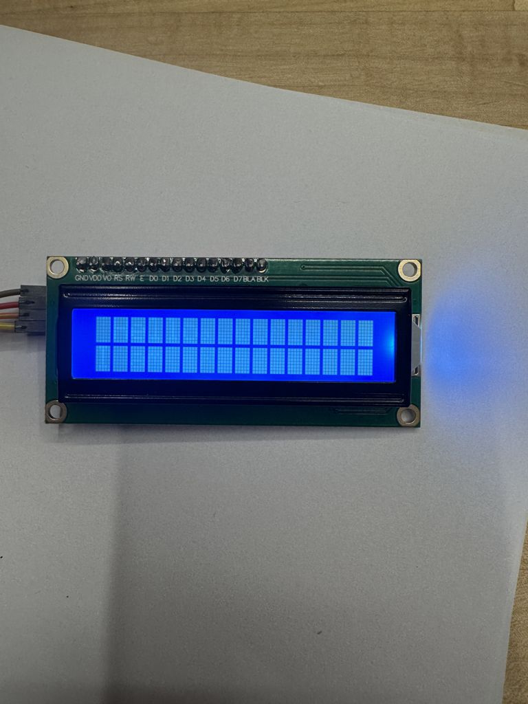
Once I plugged in the screen and confirmed that power was running, I couldn’t read any of the text unless I tilted the screen at an angle. To fix this, I looked it up online and found that I needed to use the potentiometer on the back of the LCD screen to adjust the brightness. When I twisted it, I cycled through a bunch of different light settings, ranging from bright white boxes to nothing on the screen. I adjusted it until I found the perfect setting.
Setting up Joystick
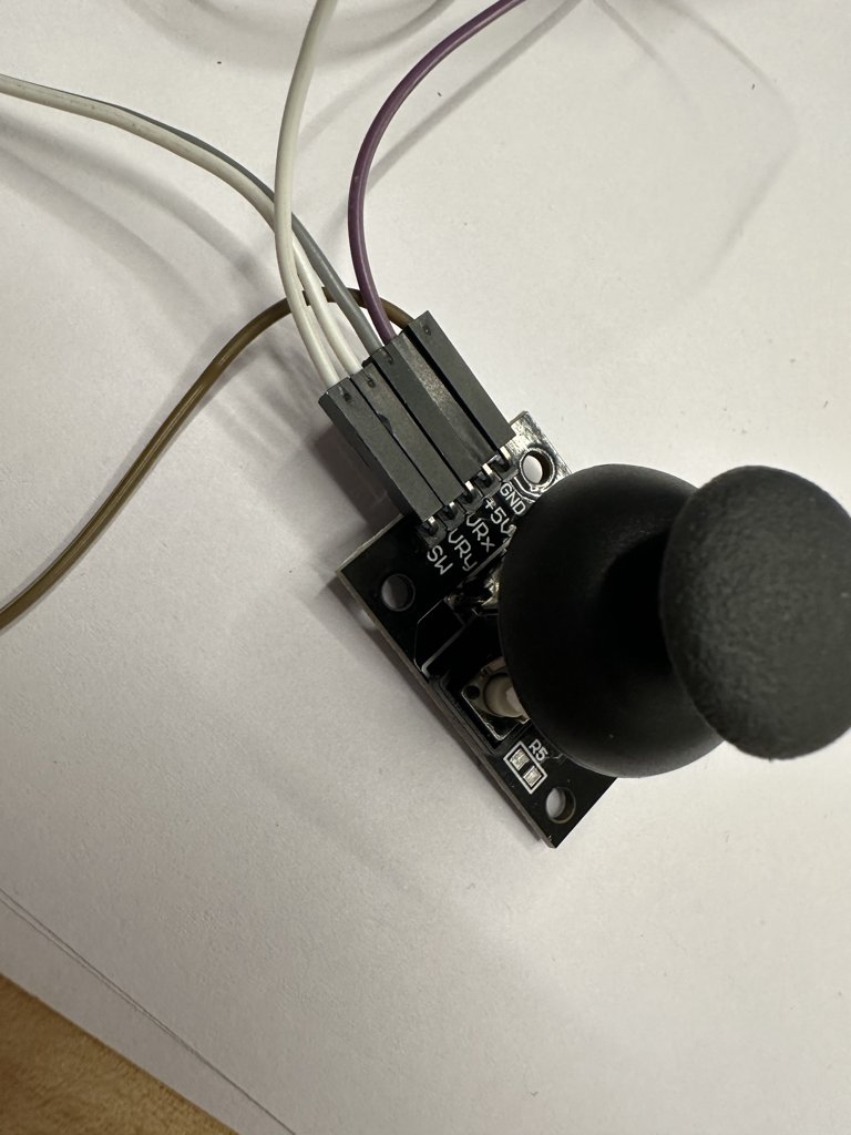
Next, I hooked up the joystick. It doesn’t require any extra components, but I did need to attach five female wires to it. The joystick has the following pins: GND, 5V, VRx, VRy, and SW. I connected VRx and VRy to analog input pins on the board, and connected SW to a pin with a pull-down resistor, so I could program it as a button press.
Connecting the Joystick to the LCD Screen
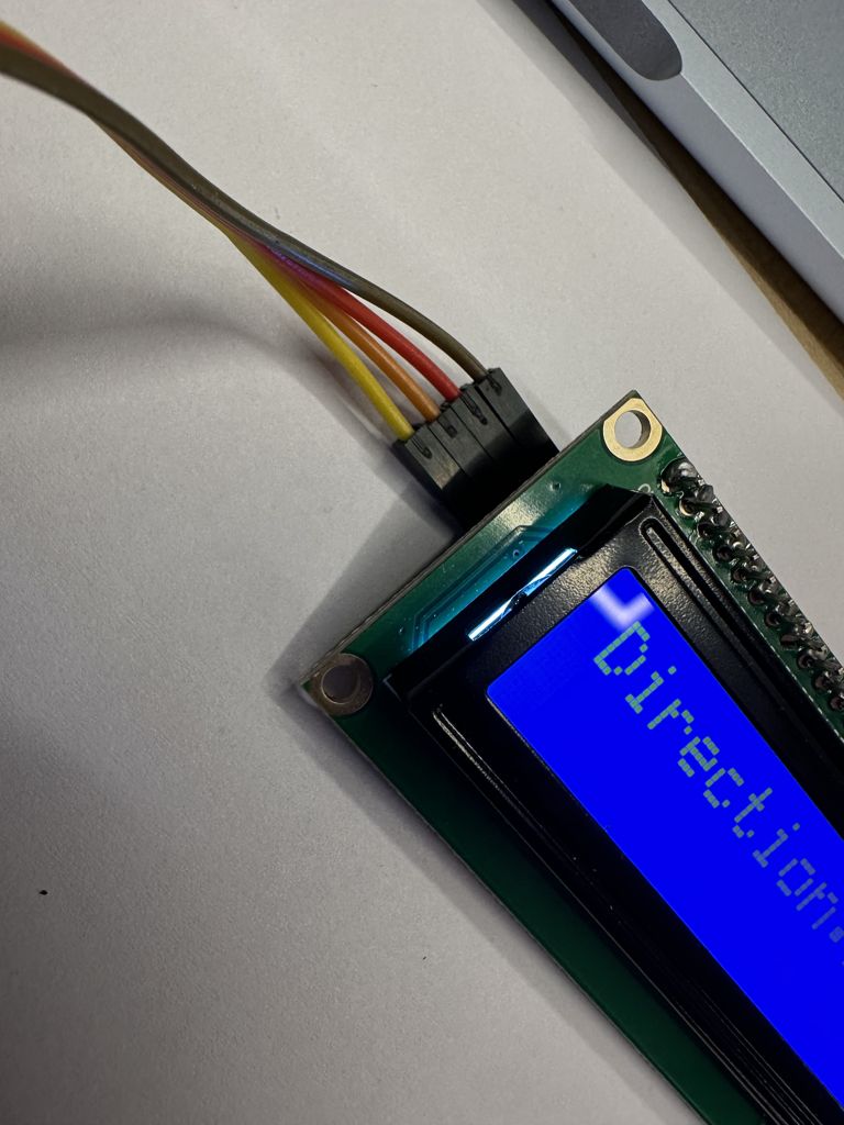
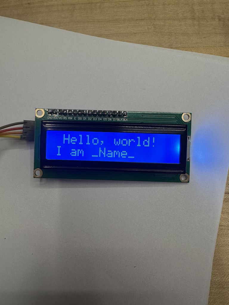
Once everything was wired, I opened the Arduino IDE and ran a program I had written previously. This program reads the joystick's motion, which gets recorded as coordinate values, and groups them into five categories: up, down, left, right, and center. Once the coordinates were grouped, the program labeled the direction and displayed it on the LCD screen. I also noticed that the neutral resting position of my joystick kept reading as “down,” and I couldn’t figure out how to fix that—but I still learned a lot.
Before getting this code to work, I needed to download a specific library to make sure this code worked. Cnce I downloaded it, LiquidCrystal I2C by Frank de Brabander version 1.1.2, The code ran perfectly fine.
      #include < Wire.h>
        #include < LiquidCrystal_I2C.h>

        // Define instance for LCD I2C display
        LiquidCrystal_I2C lcd(0x27, 16, 2);  // Change 0x27 to 0x3F if LCD does not work

        // Joystick pin definitions
        #define VRX_PIN  A0 // Arduino pin connected to VRX pin
        #define VRY_PIN  A1 // Arduino pin connected to VRY pin

        // Thresholds for joystick movement
        #define LEFT_THRESHOLD  400
        #define RIGHT_THRESHOLD 800
        #define UP_THRESHOLD    400
        #define DOWN_THRESHOLD  800

        void setup() {
          // Initialize LCD
          lcd.init();
          lcd.backlight();

          // Display welcome message
          lcd.setCursor(0, 0);
          lcd.print("Joystick Test");
          delay(2000);
          lcd.clear();
        }

        void loop() {
          // Read joystick values
          int xValue = analogRead(VRX_PIN);
          int yValue = analogRead(VRY_PIN);

          // Determine joystick direction
          String direction = "CENTER";

          if (xValue < LEFT_THRESHOLD) {
            direction = "LEFT";
          } else if (xValue > RIGHT_THRESHOLD) {
            direction = "RIGHT";
          }

          if (yValue < UP_THRESHOLD) {
            direction = "UP";
          } else if (yValue > DOWN_THRESHOLD) {
            direction = "DOWN";
          }

          // Clear and update LCD with direction
          lcd.clear();                  // Clear the LCD
          lcd.setCursor(0, 0);          // Set cursor to top-left corner
          lcd.print("Direction:");      // Print label
          lcd.setCursor(10, 0);         // Set cursor to top-right corner
          lcd.print(direction);         // Display direction

          delay(200); // Delay to reduce flicker
        }
This was my work for Input Devices Week. I used the joystick as an input, which triggered directional changes that were shown on the LCD screen. The movement was also recorded and printed in the serial monitor on my computer.
Final
Group Work: Analog Input Devices
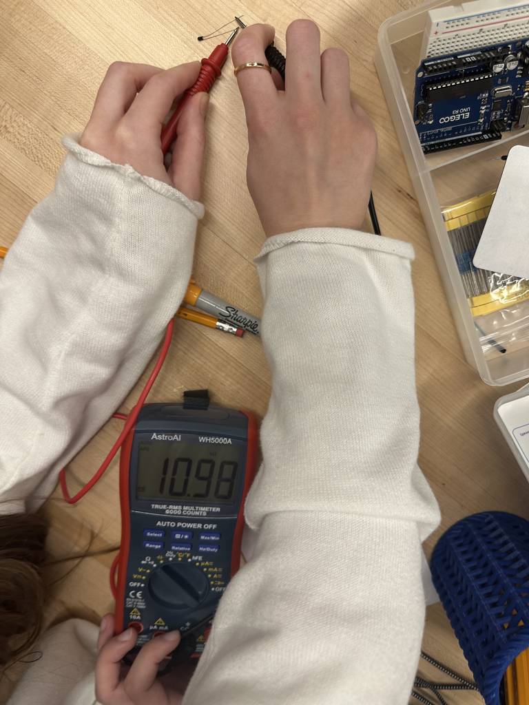
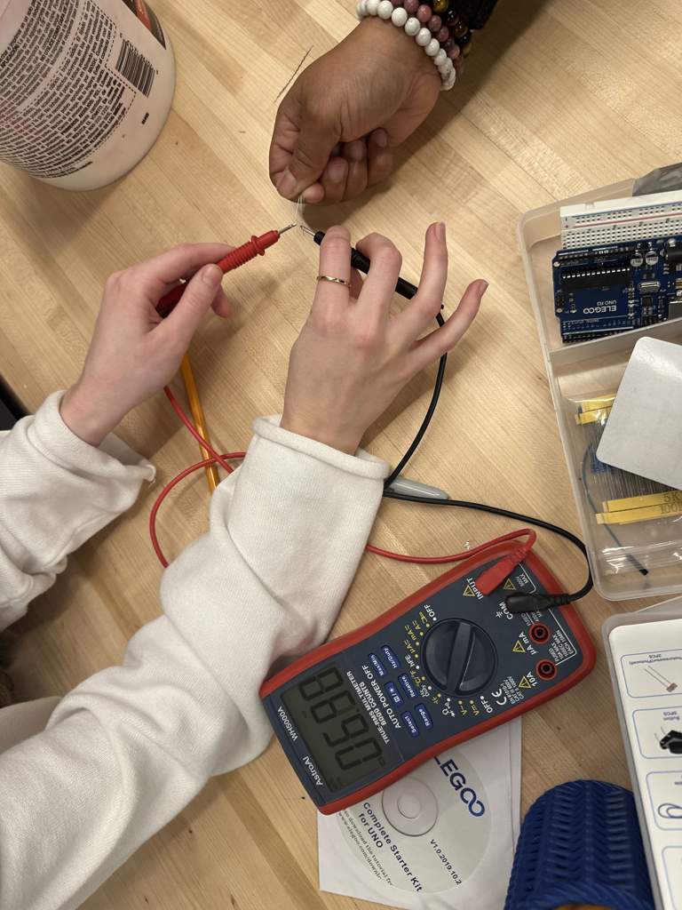
During this lab, our group explored how two different sensors respond to changes in their environment. We worked with a thermistor and a photoresistor. Both were connected using the same setup, which included a breadboard, a resistor, jumper wires, and an Arduino Uno. Since both sensors use two pins and output analog signals, we were able to reuse the same circuit and code, simply swapping one sensor for the other.
The thermistor is used to detect temperature. We tested it by first checking its reading at room temperature, which showed a value of 10.98. Covering it with our hands to trap body heat caused the reading to drop to 6.9. When placed under a cup of hot water, the value dropped slightly more to 5.9. As temperature increases, the resistance in the thermistor drops, and as it cools down, the resistance rises. This change affects the voltage and results in different analog values.
The photoresistor senses light levels. We tested it by changing the room lights, covering it with our hands, and shining a light on it. The readings changed based on how much light hit the sensor. Less light made the value go up, and more light made it go down. Like the thermistor, it gives a basic number that would need a formula to show real brightness.