12— Mechanical Design, Machine Design
Assignment
- Group assignment:
- Design a machine that includes mechanism + actuation + automation + application
- Build the mechanical parts and operate it manually
- Document the group project
- Individual assignment:
- Document your individual contribution
01— Choosing the Project
Many project ideas were presented, but ultimately we settled on a CNC wire bender. Personally, I had wanted one of these in the past too make large hanging sculptures. Metal wire when layered can be very strong and very low mass. In simpler terms you can make a very large volume with very little cost. I see a lot of potential creative projects being made with such a machine. As a group we pretty quickly came up with a number of ideas.
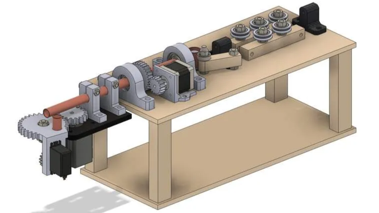
Beyond the cool factor of the project the original design that had inspired the decision had a lot of documentation as well as fully annotated STEP assembly file. This meant that instead of starting from scratch we could decrease our development time and hopefully have a working machine… in no time.
Original CNC wire bender design and tutorial
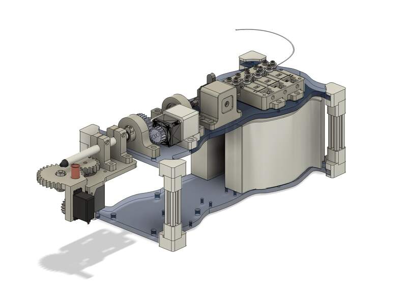
02— High Level All Mechanical CAD for CNC Bender
- 1st prototype CAD: I worked with the original STEP assembly to get the project assembled as quickly as possible. The original file was well organized, but a number of parts could be merged or eliminated to speed up the first build. I already knew from reading the comments that some sections like the feeder and straightener were badly designed so I just skipped these assemblies. As a group we decided to overhaul the feeder and straightener in the next design spiral.
- Designed 3D printed guides— the originals would have required cutting out of wood for a not great result it was easy to redesign them for 3D printing.
- Increase pillow block height— pillow bock height was increased to eliminate the need for a thin wood footer found in the original design.
- Eliminated feeder assembly
- Eliminated straightener assembly
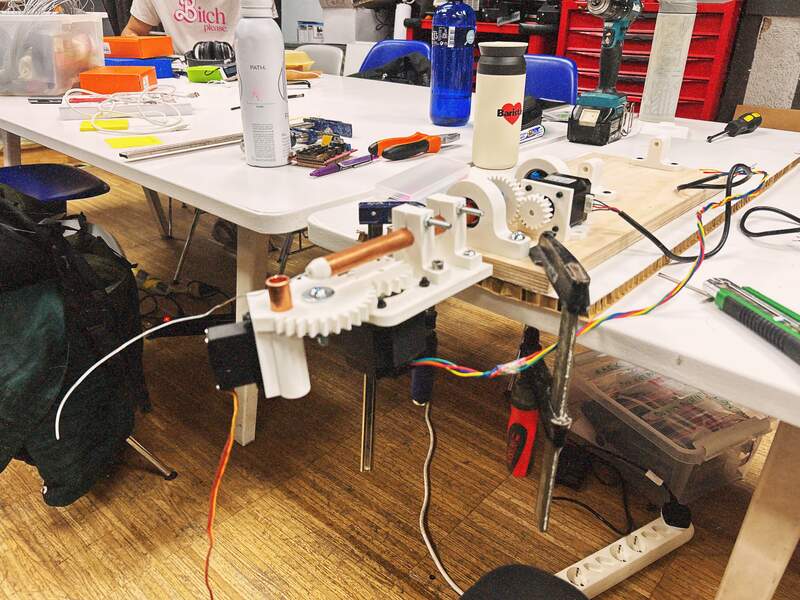
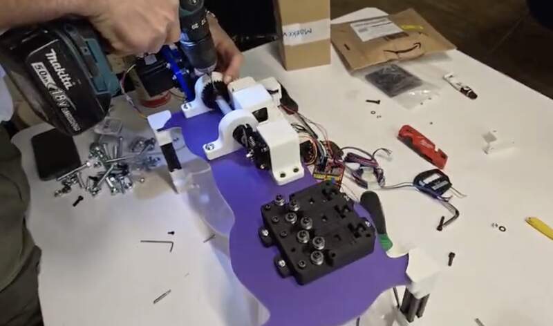
- 1st prototype assembly: I did the first assembly by mounting everything first to the copper rod and aligning everything using this as my placement jig. I only took a handful of measurement to make sure things were at least within about 2mm of their target position. In the past I would have tried to be much more precise. However, from past experience I have learned to care less about precision as an absolute goal. Precision when building only matters so much as it… actually matters. In this case I knew before I started that as long as the wire could feed straight though the machine the accuracy of the individual placed components did not matter much. This is a very important point that I think is very relevant for building things in general particularly large or complex things. This is simply it doesn’t matter unless it actually matters. Once things were glued in place Gonzalo helped a lot to get holes drilled parts screwed and whatever misc. we had to do to get the first version assembled.
- 2nd prototype CAD: The second prototype was really about adding the original features back into the design in addition to adjusting all of the important slip and press fits between things like bearings and motors. Really, all fits were wrong and were causing a lack of rigidity across the whole machine. I would attribute the loose fits to the fact that the project was designed in 2018 when printers were much less precise. Thus, on the well calibrated printers I used (Bambu A1 and X1) the parts I produced held a higher tolerance and meaning the fits were looser than the designer probably had intended them to be.
- Improved all critical component mates— This often took several iterations to dial in, but I eventually got things to fit snug, but not too snug.
- New Extruder based feeder assembly— I salvaged an old Ender filament extruder as the wire feeder. I made some modifications to the spring tension and some other mods and decided against them. Then I designed a bracket to hold the motor in place.
- Basic design changes— I the aesthetics just a bit by just adding a little filleting and chamfering. The design was filled with hard corner and edges. I don’t know why so many engineers need to be told this, but the real world is not made of hard edges… by keeping hard edges and corners you are making a visual statement. If you don’t intend to make that kind of statement that get rid of those damn hard edges.
- Lateral collar with sleeve and set screw — This was designed to hold the copper tube in position so it did not move laterally and fill the gap between the OD of the copper tube and ID of the bearing. This first version did not do this because the gap was too small to be 3D printed.
- Straightener assembly— For the straightener I did a bit of visual research and decided against designing my own from scratch. I found a very good design on Printables (link here) that I decided to modify. The bearings were special, but cheap so I ordered those on Amazon. Additionally I had to convert and re-model the original STL file to add additional mount points to the geometry to mount it to our machine’s wooden base plate.
- Limit switch mount addition to bender gear plate— I first found a limit switch in the lab and then after no luck finding a 3D model just modeled my own. Since I needed it so that I knew exactly where it where it would contact and at what angle it was important that this model was accurate. Once I had the model I placed it into position and modeled the mounting geometry into the 3D printed front plate.
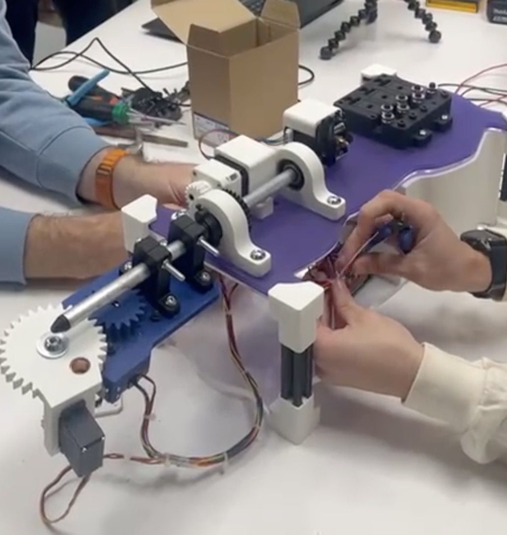
- 2nd prototype assembly: Assembly happened in phases and in some cases parts were reprinted and swapped out a few times. Critically though I got the limit switch position correct which I was quite satisfied with as it made a very satisfying *click* at the right angle position of the front bender.
- Third prototype CAD Here I was really trying to get all of the features I wanted to add implemented into the design. Unfortunately, improving feeder reliability was a sacrifice I chose to make in this phase. I did not have any solutions that I was confident would improve the feeder and I worried this was going to eat up too much time. I wanted to get the prototype into a ‘ready to present’ state so I made the following changes to the design.
- Redesign for thinner aluminum pipe— The new pipe was more rigid and because of its decreased diameter allowed for its lateral position to be properly fixed with a redesigned collar that interfaced between the pillow block bearings and the central rod.
- Fully redesigned sleeved lateral collars— This was the ‘trivial’ part of the design that ended up neither trivial in design process nor trivial in function. It took 5 or 6 iterations to get the design and fit right. This helped to make the machine far more accurate as the pipe was now properly fixed from unwanted movement.
- 2020 extrusion column /corner mounts— The corner pieces allowed the machine to sit on a table and also provided room underneath to mount things like electronics. In my mind this was an essential edition to make the machine feel self contained and usable. While I did not miss anything in the initial design I did have to adjust and print the female fit that interfaced with the 2020 extrusion several times until it had the right fit.
- Counterweight gravel bins— The corner brackets allowed me to add a second level level so that I could add counter weight bins to keep the machine from pitching forward. This eliminated the need to awkwardly clamp the machine to a table top. Similar to the lateral collars, their was bit more nuance to this design than I initially expected. The bins needed to not be overbuilt (so they printed quickly), but also not under built (so they would not split as they held the weight).
- 3rd prototype assembly: This assembly was a partial rebuild as many components had to be reprinted for the new rod diameter. Half of it didn’t get integrated as the machine got taken home and it was already the weekend.
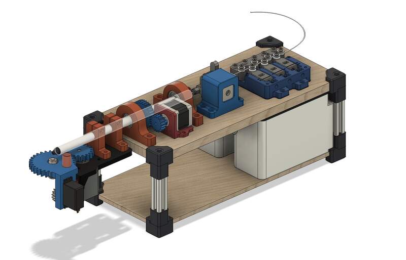
- Fourth prototype CAD: This was really a mad dash and was completed over the last two days of the project. Here we were trying to add an interesting visual identity to the design and also incorporate some final key features. All of the visual decision for this version were made by Camilla. The gear head assembly was mostly ED’s project that I jumped in on.
- High torque gear head and mount for stepper motor— Here Ed sourced and 3D printed a predesigned 3D printed planetary gear head reducer for our X axis NEMA 17 stepper. This was a key addition to get the X axis working by increasing its torque. We then were tasked with redesigning its mount for the gear that we needed for this. This was a significant design challenge so I ended up taking this on personally. Without going into too much detail I found a solution that required minimal revisions to effectively mount the gear to the gear box rotor head. After this I just had to design a new holder for NEMA 17 motor which was an edited version of the NEMA 17 feeder bracket I designed previously.
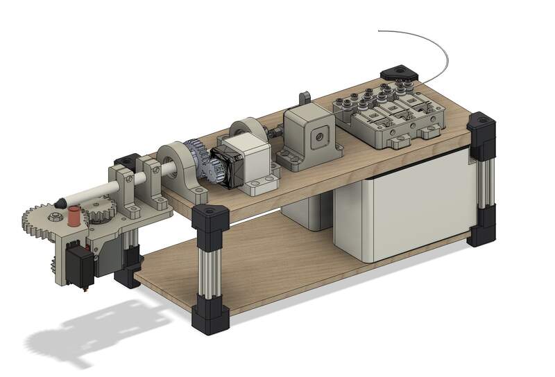
- Acrylic redesign— The redesign of the CNC for the acrylic plates required a number of components again from scratch including the: 2020 extrusion column mounts and Counterweight gravel bins, X axis rotary motor mount. Since the original design only loosely followed the alignment of the original CAD model I also needed to finalize and confirm fastener types placement and hole clearance.
- Final assembly: Cutting the acrylic was very difficult and this was mostly done by ED and Mark with a little help from me. Thankfully after hours of trouble shooting Ed got it cut the next morning and all of my sizes were correct! The final assembly went surprisingly smooth me and Mark took a few videos and pictures and carefully rebuilt the whole machine. We had to be very careful when pressure fitting the edges on the acrylic so as not to crack it.
03— Review and Improvements
We would really have to get the whole machine working again for me to know what would need to be changed in a later version. There are definitely a long list of small changes and adjustments that I would make if I were to design a new version of the project. However, none of these changes capture the much more critical question of wether this design can actually do what it is supposed to.
Thus instead of listing off changes maybe I might list off a new set of design requirements by order of importance.
- The machine should operate predictably with its control software be able to bend and feed several specified wire types and diameters.
- The machine should be self contained and streamlined visually— something can set on a table and get running in 5 minutes.
- Lower cost and more commonly available hardware should be used across the design
- An integrated cutter and spool feeding system should be added to reduce user intervention.
04— Final Reflection + Group Page
Im proud of what I was able to accomplish, but I wish I had not been so rushed the last 2 days. The final push made me have to skip testing some components before they went into the final machine which thankfully was only a problem for the mounting bracket for the rotary stage. I was stretched very thin to make sure that everything was going to fit and work properly. I actually was reminded once again to trust my gut instinct about how long projects like this actually take. It can be quite extreme how much time these small seeming design details can be to sort out. Alas, it did feel validating because especially with the stepper drivers I could see that it wasn’t just me building machines is very hard.
One thing I was able to put into practice was integrating my past knowledge of working with large CAD assemblies into this project. I was able to work far faster and far less methodically than I ever have at getting the file together and integrating/ editing design within it. So doing this project definitely increased my confidence in throwing together and managing large assemblies in Fusion.
I don’t pushed myself too much technically with this project and in some ways I I wish I did. I wish I had spent more time trouble shooting the kinematics so I could have built a better understanding of working with steppers. If I had I probably would have been of more use working helping to root out the issues we were having with the stepper motors and drivers.
Project Files