11—Networking and Communications
Assignment
- Group assignment:
- Send a message between two projects
- Document your work to the group work page and reflect on your individual page what you learned
- Individual assignment:
- design, build and connect wired or wireless node(s) with network or bus addresses and a local interface
00— Reflection
This was a busy week filled with fab academy things that were different than the topic this week. I chose to spend the last week sorting out my custom PCB for my final project. A lot of this time spent was figuring out how to efficiently get custom components into Flux.ai. I also edited my initial circuit plan several times and was able to draft about 75% of my final board so I should be on track to send it out by the end of the week.
Luckily through the assignment this week I discovered an error in my initial design. This was small, but would have been critical and was something I would have not found without direct testing. The error was handling my I2C lines that links the top and bottom control board the same way. I created the other I2C lines. basically the linking line should not have a 3V3 rail because it is its own hub with its own power source and doing this just back feeds into the Xiao’s 3V3 port which is not something I want to do.
So anyway next step for final project are
- Finish and send out for manufacture final_project_PCB_v1 by end of week
- Draft software diagram to understand what features libraries / functions are needed to get the whole thing working
01—Group Assignment
For the group assignment we had to link two of our custom boards together to demonstrate that we know how to properly use a communication protocol. Here we communicate over wifi using a TCP server and another as a client. This utilized my board and Gonzalo’s board. The takeaway from this experiment is that the ESP boards handle wifi communication very reliably. It is quite easy to get this functionality up and runnning and is surprisingly dependable. Personally though especially for my project I am pretty weary of relying on any wireless communication protocol for a project that is installed somewhere because regardless of how stable it is it still another point of potential failure. If running wire for communication is possible I will.
02— Wired Communication
Core Concepts
- Serial vs Parellel
- Serial sends multiple channels of data on the same line
- Parallel is old school and just uses one line per channel
- Synchronous vs Asynchronous
- Asynchronous (no clock line)
RX/TX/UART
- Synchronous (clock line)— I2C
- Asynchronous (no clock line)
UART or TX/RX
- UART: Universal Asynchronous Receiver/Transmitter
- Is asynchronous and composed of a
TX lineandRX line
- Bit banging UART
- Bit banging is just a way to force a non serial pin to read and or send serial by just getting it to send the voltages.
- Since it does not have a clock line baud rate is particularly important
- Relies on the built in Arduino serial library for communication
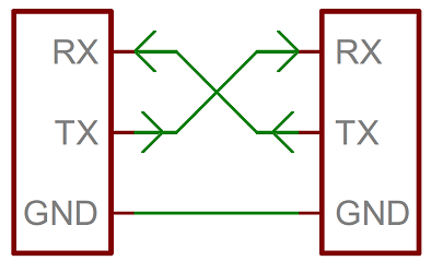
- Below is a diagram of a two wire RX TX configuration
- Example Arduino code (Barduino)
void setup() // interesting there is a delay and print in the setup I guess you can put anything in setup as long as it only needs to run once
{
  Serial.begin(9600); // sets baud rate or bit rate the console reads at
  Serial1.begin(9600);

  delay(1000); // delay before start program
}

void loop()
{
  Serial1.println("Andrews Board"); // this print variation apears to just be for ASCII

  delay(1000);
}
I2C / IIC Communication
Data Lines
I2C Has two lines SDA — Data and SCL— Clock
I2C Addressing
- I2C chips use a hexadecimal address
- Addresses are typically preassigned. Some devices have dip switches / solderable zones to tweak the address.
- I have been told additional virtual busses can be created on other virtual GPIO to handle devices with the same address. I am not sure about the limitations here or where to examine this in a specification sheet.
- I2C Expanders also exist to handle the addressing issue.
- Technically the addressing system allows for 127 devices.
SPI Communication
- Harder to program (flash uses SPI)
- Higher bandwidth
- Other LED styles (besides Neopixels) use SPI
03—Wireless Communication
Wifi
- 2.4GHz or 5GHz
- Wifi as a communication protocol does not need to actually connect to the web. It can be utilized through a soft access network
ESP-Now
- Works on ESP boards
Example ESP32 Wireless Code from class
    #include <WiFi.h>
    #include <PubSubClient.h>

    const char* ssid = "Iaac-Wifi";
    const char* password = "EnterIaac22@";
    WiFiClient wifiClient;

    const char* mqttBroker = "test.mosquitto.org";
    const int   mqttPort = 1883;
    const char* mqttClientName = "Andrew"; //Change your client name
    const char* mqttUser = "";
    const char* mqttPass = "";
    const char* subscribe_topic = "fabacademy/led/josep"; //Change the topic
    const char* publish_topic = "fabacademy/led/andrew;)"; //Change the topic
    PubSubClient mqttClient(wifiClient);

    bool state = false;
    int LED = 48;
    int BUT = 0;

    void setup() {

    Serial.begin(115200);

    pinMode(LED, OUTPUT);
    pinMode(BUT, INPUT);

    // Connect to wifi
    WiFi.mode(WIFI_STA);
    WiFi.begin(ssid, password);

    while (WiFi.status() != WL_CONNECTED) {
        delay(500);
        Serial.print(".");
    }

    Serial.print("Connected to ");
    Serial.println(ssid);
    Serial.print("IP address: ");
    Serial.println(WiFi.localIP());

    // MQTT setup
    mqttClient.setServer(mqttBroker, mqttPort);
    mqttClient.setCallback(callback);
    }

    void loop() {
    // Check if we are still connected to the MQTT broker
    if (!mqttClient.connected()) {
        mqttConnect();
    }

    // Let PubSubClient library do his magic
    mqttClient.loop();

    // Add your publish code here --------------------
    if (digitalRead(BUT) == LOW && state == false) {
        publishMessage(publish_topic, "on", false);
        state = true;
    }

    else if (digitalRead(BUT) == HIGH && state == true){
        publishMessage(publish_topic, "off", false);
        state = false;
    }
    delay(100);
    }

    void mqttConnect() {

    while (!mqttClient.connected()) {

        Serial.print("Attempting MQTT connection...");

        if (mqttClient.connect(mqttClientName, mqttUser, mqttPass)) {

        Serial.println("connected");
        mqttClient.publish("hello", mqttClientName);

        // Topic(s) subscription
        //mqttClient.subscribe(send_topic);
        mqttClient.subscribe(subscribe_topic);

        } else {

        Serial.print("failed, rc=");
        Serial.print(mqttClient.state());
        Serial.println(" try again in 5 seconds");
        delay(5000);

        }
    }
    }

    void callback(char* topic, byte* payload, unsigned int length) {
    String incommingMessage = "";
    for (int i = 0; i < length; i++){
        incommingMessage += (char)payload[i];
    }
    Serial.println("Message arrived[" + String(topic) + "]" + incommingMessage);
    if(incommingMessage == "on"){
        digitalWrite(LED, HIGH);
        Serial.println("LED ON");
    }
    else if(incommingMessage == "off"){
        digitalWrite(LED, LOW);
        Serial.println("LED OFF");
    }
    }

    //======================================= publising as string
    void publishMessage(const char* topic, String payload, boolean retained) {
    if (mqttClient.publish(topic, payload.c_str(), false))
        Serial.println("Message publised [" + String(topic) + "]: " + payload);
    }
04— Board to board I2C communication example
- Created code from Cursor using Claude Sonnet 3.7
- Cursor prompt: was initially…. “please generate code to send I2C communication between two Xiao. The master and slave boards are two Xiao boards based around the ESP32 C6 chips by Esspresif systems. I need a simple check over serial to confirm that the master and slave board are receiving messages.”
- From the two programs I generated and trialed several iterations. This was all tested using a commercial shield for the Xiao ESP32 C3 and my own custom evaluation board with built in I2C. I went back and forth with prompting and uploading the code. This was mostly in vain, but through this process I might have discovered an issue with how implemented the I2C communication between boards on my final project. For this line I included a power rail to 3.3V like had done with all other I2C connectors. I think this is wrong for this connection because this I2C device happens to have its own separate power as they are two different hubs that have separate power.
- Cursor prompt: “please carefully consider the configuration I have just outlined previously and take the chip types into account and use only common communication libraries for I2C like the Wire.h library. Do not overcomplicate this I simply need a message between the two boards to confirm that A the master is receiving the message from the slave and B the slave is in fact attempting to send the message”

- Cursor prompt: “please carefully consider the configuration I have just outlined previously and take the chip types into account and use only common communication libraries for I2C like the Wire.h library. Do not overcomplicate this I simply need a message between the two boards to confirm that A the master is receiving the message from the slave and B the slave is in fact attempting to send the message”
- After about an hour of trial and using both Sonnet and chat GPT. I was able to prove that both boards were at least trying to send out information through I2C. This is because I was able to get the boards to send serial when disconnected to confirm that serial on both was at least working. I could confirm this from reading the serial on both devices. So this at least proved to me that the issue was unlikely to be caused by the MCUs themselves.
- To further simplify debugging I switched to a breadboard with the 2x Xiaos and dupont cables connecting them. This way I could rule out my eval board as the source of the communicationproblem.
- I did further research to confirm my wiring which was easy because I2C connections are simple. In this case since I had two MCUs I decided that the lack of pull-up resistors on the SDL and SDA line were very likely a non issue.
- With the wiring confirmed and the MCUs serial functioning I did some basic research and didn’t find any specific examples relevant to my exact Xiao boards. I did however, find this tutorial which I read all of the way through. I figured at this point I might as well run the code unedited… It worked!

- Now that I had code confirmed to work I decided to test the configuration on my custom hardware. It worked! As you might notice in the photo I cut the power line on the grove cable I am using. This was done earlier because I thought this might have been the culprit of the communication errors.
- Now I am going to test if the communication is broken if I reconnect them. Since the I2C on the custom board is connected to the 3.3 V port off the Xiao the Xiao on the custom board cannot also be connected to power since this port will be now acting as an input. This did not work. I have had issues powering the Xiao through its 3V3 port so I don’t plan to do further testing. Suffice it to say I will be modifying my final board to not send power over its Slave / Master Communication line.
- Here is the example code used.
SLAVE CODE
#include "Wire.h"

#define I2C_DEV_ADDR 0x55

uint32_t i = 0;

void onRequest() {
  Wire.print(i++);
  Wire.print(" Packets.");
  Serial.println("onRequest");
  Serial.println();
}

void onReceive(int len) {
  Serial.printf("onReceive[%d]: ", len);
  while (Wire.available()) {
    Serial.write(Wire.read());
  }
  Serial.println();
}

void setup() {
  Serial.begin(115200);
  Serial.setDebugOutput(true);
  Wire.onReceive(onReceive);
  Wire.onRequest(onRequest);
  Wire.begin((uint8_t)I2C_DEV_ADDR);

/*#if CONFIG_IDF_TARGET_ESP32
  char message[64];
  snprintf(message, 64, "%lu Packets.", i++);
  Wire.slaveWrite((uint8_t *)message, strlen(message));
  Serial.print('Printing config %lu', i);
#endif*/
}

void loop() {

}
MASTER CODE
#include "Wire.h"

#define I2C_DEV_ADDR 0x55

uint32_t i = 0;

void setup() {
  Serial.begin(115200);
  Serial.setDebugOutput(true);
  Wire.begin();
}

void loop() {
  delay(5000);

  // Write message to the slave
  Wire.beginTransmission(I2C_DEV_ADDR);
  Wire.printf("Hello World! %lu", i++);
  uint8_t error = Wire.endTransmission(true);
  Serial.printf("endTransmission: %u\n", error);

  // Read 16 bytes from the slave
  uint8_t bytesReceived = Wire.requestFrom(I2C_DEV_ADDR, 16);

  Serial.printf("requestFrom: %u\n", bytesReceived);
  if ((bool)bytesReceived) {  //If received more than zero bytes
    uint8_t temp[bytesReceived];
    Wire.readBytes(temp, bytesReceived);
    log_print_buf(temp, bytesReceived);
  }
}
References / resources
Project Files
All project files included in body.