3. Computer controlled machining
Goals for the week:3
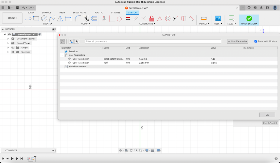
When I started to design my laser cutter project I created Parameters of the material (card board) in 4.15mm and the kerf in 0.565mm.
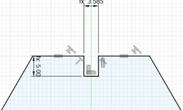
After creating the parameters I made a gap in between of the top line of my design. I did that by using the rectangle tool and modifying the measurements to the parameters I made.
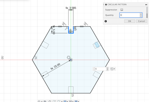
I then made my design into a hexagon like shape with the same gap lengths. I did that by using the circular pattern tool and setting the quantity to 6.
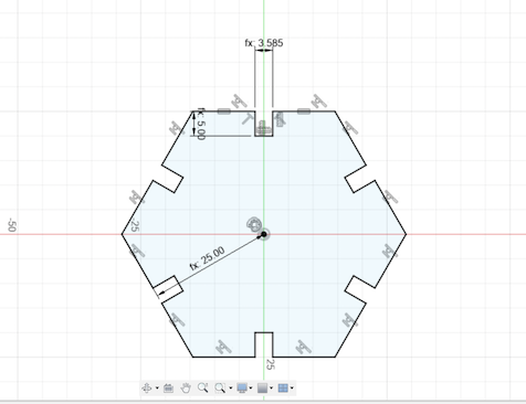
As shown in the image above after creating the gap lengths I used the trim tools to make the gaps in the shape.
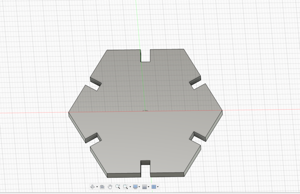
As the sides of the shape have the same gap length I used the extrude tool to have a better view of it in a 3d like model.
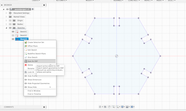
When I've finished the design in Fusion 360 I exported as a dxf. I did this by right clicking the sketch folder on the left hand side of the screen and clicked on the dxf file to export it.
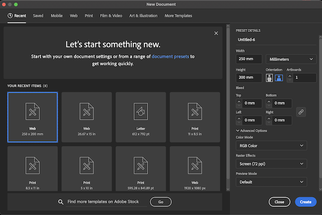
I then gone onto Adobe Illustrator and created a new file for the dxf file.I made it in millimeters to help compress the design.
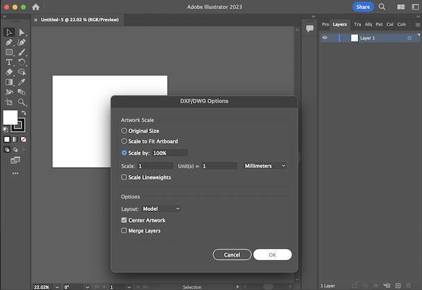
After making the file I dragged the dxf file into Adobe Illustrator. As I dragged the design file into Adobe I checked the dxf/dwg options by having the measurment in millimeters,the layout as model, and the center artwork icon checked.
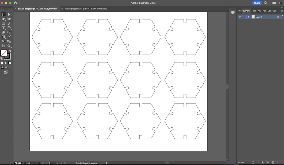
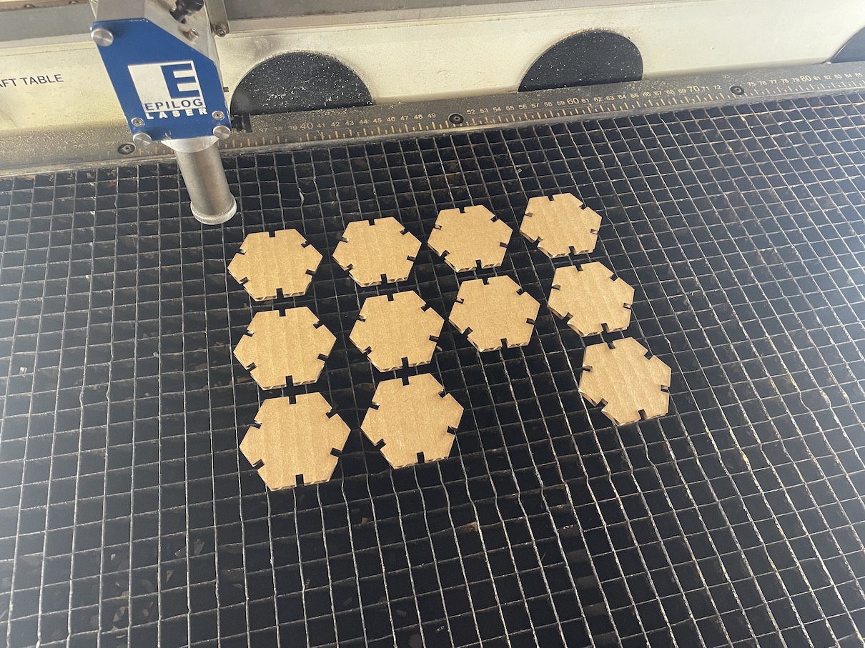
As everything was set I had rearrange the design in the left corner to help center it when sending it to the last printer.Then I copied and pasted the design in three roles of four equallying twelve in total.

The design I made had to have the right frequency , power , and speed. With the help of the website called Epilog Dashboard I made the speed 30 ,the power 40 , and the frequency 10. I then made sure the Beziers on and Air Assist.
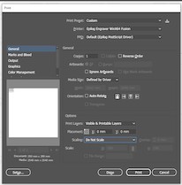
When the design is sent to the laser cutter printer I made sure the print layers were visible and printable layers and the scaling was on do not scale.

I then made sure the laser printer was on and operational. I did this by turning on the machine and wait a couple mintues.

As the printer is starting I also turn a button to the right and wait for a green light to shine to indicate it's ok to use the machine.
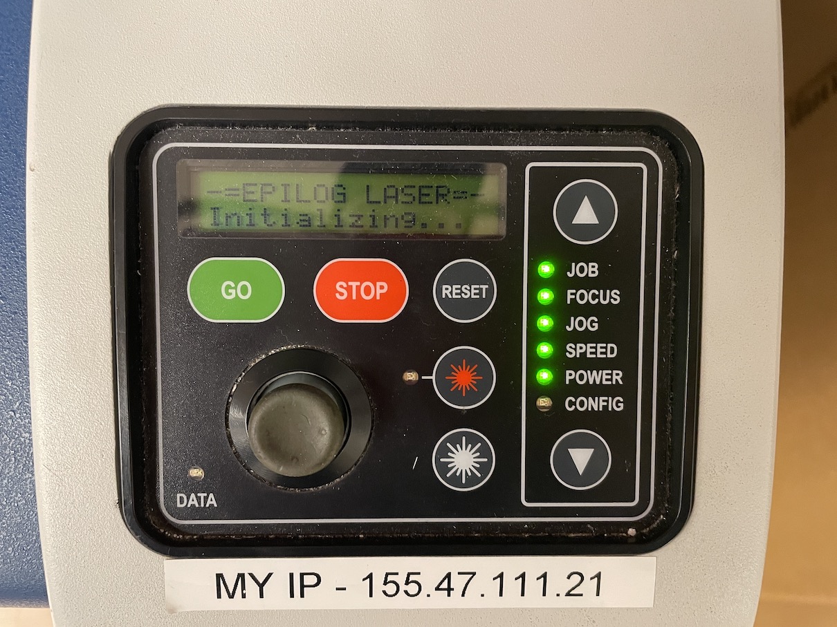
After the printer turning on the little pannel began to initalize the epilog on the website.

As the printer is almost ready I placed the material to be cut into the printer. The material our lab was cardboard.

In the image above shows of a red dot laser showing where the design will be cut. There is also a metal triangle on the side to help measure the distance between the laser and the material.

After setting the distance between the material and the laser I rearranged it to save material for others. I did this by moving the laser after the previous project.

When the laser was rearranged I turned on the ventalization to help with getting rid of the toxic fumes.

On the panel on the laser cutter I set the job to 600 dpi.

I then clicked start on the panel to begin the process to cut out the design.
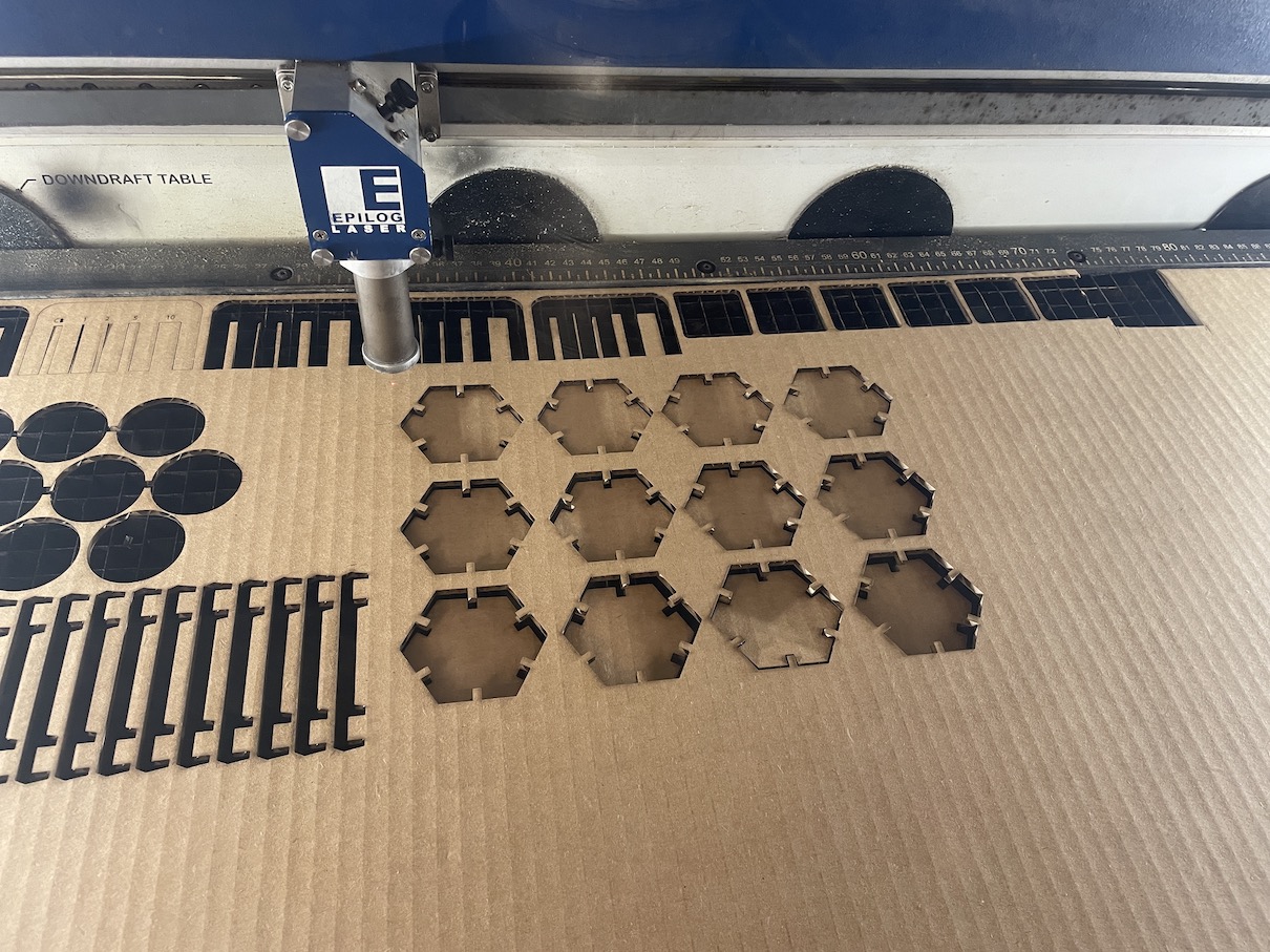
As you see when the cut out of the design is done it automatically stops.

After the design was cut I took out the card board exterior from the bottom of the laser cutter.
In the laser cutter after the cardboard is removed is the the design. I then take them out and start figuring out what to build of it.

When all the steps are completed and building the design itself here is the end product.