Description
As the heading suggests a dome dryer with an all new climate control system to dry specific veggies,dry fruites and chillies etc. The Project will utilise a temperature-humidity sensor,a motor and a controller with a wireless interface like bluetooth.
The dryer will perform a climate control setting with respect to the external temperature and create an optimal environment inside to dry food.
The problem arised at Vigyan Ashram while using the dryer. The requirement was putforth to Fab lab to find a solution. The curent options in the market available are microwaves,generic dryers etc.
Here the concept is to trap suns energy and dry food in an efficient way so that the food could be processed and sent for packaging.
Currently the project is in its infancy and doesn't have some information posted. Further developments of the project will be posted on this page accordingly.
Project Plan and its use
This project will be utilized at Vigyan Ashram for its needs to dry perishable items.
Later will be sent for testing to a client who has a similar prototype for drying.
This is just an improved version of the previously built Dome Dryer and it a group project which is sub-divided into different smaller projects.


Project Sketch

Date:- 01/03/2022
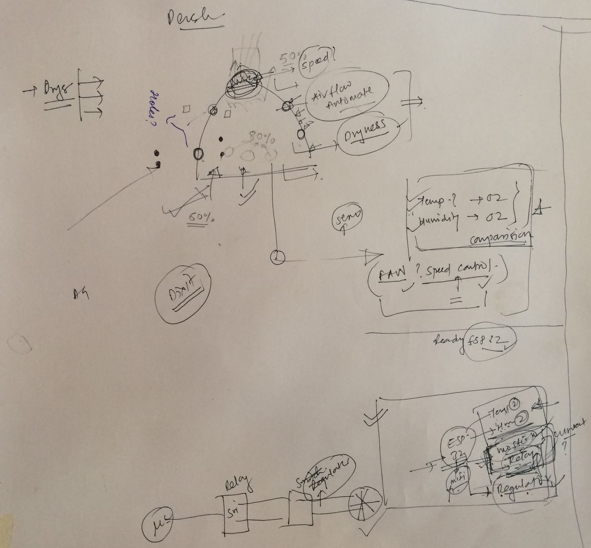
Today we were dicussing about the smart dome dryer and the real objective. The instructor held a dicussion about the project eventually asked about the requirements of the project.
What are you doing? was the question that he asked about the project. Then some debate went through after which I was asked to create a block diagram. The image below shows the disscussion. most probably phase 1 of the project will star by next during electronics production.
Date:- 21/04/2022
The Machine week was and was quiet exhausting I still have alot of work to do my review didn't go well either but I pushed through my short term goal is to enter global reviews most probably I'll complete this task by 25/04/2022.
The Dryer plans are going good in the output devices week I was experimenting with a single channel realy module on a ESP32 devkit it worked fine and I'm adding this to my circuit schematic also. The only thing I might have to pass on the electronics side of things is seep control of the fan that I'm going to use on the dryer.
Previous updates on the dryer after drilling some holes on to the polycarbonate shell we saw that there a decrease in efficiency of the dryer, Since its a joint project I have to coordinate with the DIC (Design Innovation Centre) interns also still the reason for the decrease in efficiency is not eminent.
Date:- 23/04/2022
Made some minor changes to the project page added reference links now I'm working on the other aspects like wet bulb priciples.
Flow Chart

Electronic Design
An electronic schematic helps the viewers to identify the parts that are going to be used in a graphical way it also indicates the connections that are necessary.
I'm using some electronics compononets here and would like to show what I have used for this project.
An image below shows the components and there connection on the pcb.
If you would like to access my design I will be linking it down in the original design files section.

Principles
Dry Bulb and Wet bulb
The measurement of relative humidity (%) is the key to this project. For this we have to do some analysis and generate some data
The project works on the principle of psychometry were we have a psychometric chart that is used in weather stations across the world.
There is a pair of Dry and Wet bulb. The dry bulb measures the ambient temperature where as the wet bulb is wrapped in a muslin cloth which is inturn dipped in water about 80% of the bulb is dipped in water and measures the temperatues.
I/O Devices
For the project I did select DS18B20 Sensor which is an input device in this project I tested these sensors out and also did something called tagging.
To know more about this sensor I have documented all rest in the input device assignment. To know more please visit the Input Devices week by Clicking here.
As for the Output Device is concerned I haved tested the device but it was included into the project at the last minute. The testing video shows the working of the output device. I have documented and tested the output device during the ouput device week.
If you would like to access output devices week please click here.
Date:- 02/06/2022
A PCB Update after the I/O week assignment I almost had my project board ready I got the compionents test and readied eveything for system integration.
During this time one of my I/O pins got damaged and had to replace them instead of replacing the pin since it was tougher and time consuming I thought of designing a new board with a shield type design in mind eventually it got through today I drill the through holes of the shield or peripheral board which will house the sensors.

Casing update
A 3D design for casing was done on Fusion 360 I was thinking to use Acrylic for the casing but I'm exploring the materials we have that can be cut on a laser,I'm open to suggestions and stories for the project.
The case design that I have is a simple box like design but would like to make it look asthetically more pleasing will the dne on a laser cutter and will be pasted with vinyl stickers this I hpe would give it a new look and feel.
After this I would move on to protype the design and see how does it look.
Date:- 03/06/2022
Tested electronics there was an issue with the OLED other than that all the components are working 50% system itegration achieved.
Update on casing ready to rdesign the casing of the priject the software to be used is Fusion 360
Wiring and testing
While testing the project it was fine the main problem arises in system intregration where overall components have work together.
The main issue is that wifi isn't working properly with OLED and so I have to find another way to figure out the issue.
Now to talk about wiring, its all a mess! I can't understand how to do the wiring of the project till now lets figure out something for the project during the design phase of the casing.
Date:- 14/06/2022
The project was in a downward spiral so I came up with another plan. The odlder PCB failed so I had to design a new one.
I even redesigned the casing with some help from others.
The images below will shows the new board inside the newer casing.

You can also see a bit of cabling here.
The only happy news is that thr OLED is now working and I have taken it back into the system.
A little bit of fabrication at the workshop
For the project to work properly we had to mount the exhaust fan at the top of the dome.
Presently there are no holes on the metal plates to hols the flanges of the fan so we had to think of a work around.
Then thanks to Purnesh who gave some advices on mounting the fan to the metal plates present at the top.
The work to almost a day but the fan was mounted. Learnt to drill holes using a bench press drilling machine.
Purnesh also helped me tweek some of the cabling and putforth an advice to pass all the sensors from the top.
I would say this day that is 13/6/2022 was one of the most productive days in the project.
I also learnt that fabrication at a workshop is a serious business.
Some images below showing the fabrication at the workshop.


Bill Of Materials
The BOM of this project is given with a link below.
To be exact the project costed around 2600 INR which is around 35 USD.
Click here to download the BOM.
Testing Video
Here is the testing video of all the components.
Presentation Silde and Video
I'm linking the presentation slide and video for your reference.

Acknowledgement
It was a lot of to complete this project and I would like to acknowledge the time and effort put into to this project by others also.
Each and everyone mentioned in this section was a helping hand and a greater support to while working on this project.
First and foremost I would like to thank my Instructor Mr. Suhas Labde who helped at the right moments and pushed me with some encouraging words.
Sir I thank you since you giave me the direction to work in with the project.
Secondly my fellow Fabacademy mates without all of you I wouldn't have done it.
A special note to Kiran Wakchaure sir and Kishore sir who helped me design and build my project even in the last minutes.
Special thanks to Purnesh and Ashish at the workshop for providing me with ideas and advices and fixing the flaws in the project.
I would also like to thank my mentor Mr. Arun Dixit who assigned me this project. The advices that I got were top notch.
Original Design Files
All the original Design files and program are linked here for download.