Final Project
Fabulous Notifier
For the final project, I have created the following two products:
- Fabulous Notifier: A desktop device for showing the smartphone notifications that are most important to the user in order to reduce distractions and get things done.
- Fabulous Notifier App: An Android app for:
- Connecting to the desktop device using bluetooth;
- Selecting the apps which notifications will be tracked;
- Assigning keywords and values to the notifications;
- Sending signals to the desktop device each time notifications whose contents match the configured keywords.

Conceptual Design
The main idea behind this project is to find a way to minimize the following problematic situations:
- Getting distracted by constant unnecessary notifications.
- Missing important notifications.

In order to accomplish that, the plan is to create a desktop device capable of interacting with smartphones and showing filtered notifications.

This device has two main components:
- A clock dial with Labels for different statuses.
- Clockhand that shows the current status when an important notification is received.
In my case, I defined the following statuses:
- Important: A very important notification has been received, for instance: messages with mentions or with keywords such as ‘important’, ‘bug found’, ‘help’, etc.
- Eat: Notifications related to online food delivery apps, or whatsapp messages with phrases such as “Time to eat”, “Lunch time”, etc.
- Order: Notifications related to online orders. For example: “Your order has been canceled”
- Silence: Used when someone else in my home is having an online meeting and the volume of my speakers are high.
- -: Initial status. When you just turn on the device, the clockhand should be pointing to this status.
- Bank: Notifications related to my bank Account. For example: “Your salary has been credited!”
- Show: Notifications related to live streaming apps (twitch, youtube, instagram, …), such as: “Streamer123 is live now”
- Meeting: For Google calendar notifications mostly.
This is based on my own needs, but the idea is that other people could define their own statuses, and also design and fabricate their own dials.
Additionally, an App will be needed for managing notifications ands statuses. I will expand on that in the following sections.
Fabulous Notifier Desktop device
External case design
I’ve been thinking on the appearance of my final project since the first week of the Fab Academy. At that time it was difficult to imagine how it would look like because I didn’t know how many components the device would have inside… but in spite of that, I had some design requirements in mind:
- It should have an appearance similar to an analog alarm clock.
- It should be small enough to be placed in my desktop.
- The clock face should be easily replaceable.
With that in mind, I created this model on week 2:
This model was far too simplistic, since at that time I had no knowledge about digital fabrication techniques. Really, I had no idea about how to fabricate this design  .
.
A few weeks ago I decided to continue working on the design since I already had the electronics and app designs for this project. This time identified the following components:
- A 3D printed (12cm x 12cm) base with supports for all the walls/faces of the device and also for the stepper motor.
- A 12cm x 12cm clock face with an inclination of 10º. The clockface is made of a 3mm MDF sheet.
- Lateral, back and top faces made of a 3mm MDF sheet.
- 3D printed clock hand.
Feel free to interact with the model above. If you hide the walls you will see the interior of the device:
Although this design was really useful for testing the functioning of different parts of the project - Movement of the stepper motor and clock hand, debugging the embedded code, testing integration with the mobile app - , the design was quite simplistic again… It was basically a 12cm x 12cm x 12cm wooden cube .

I noticed that the size of the device could be reduced because the electronic components inside didn’t take up much room. So I ended up changing the 3D printed base size to 12cm x 9cm. Additionally, I added slots for vertically inserting the main PCB and the bluetooth module.
I also decided to replace the wooden back and top faces with a curved 3D printed backface that fits perfectly into the back part of the 3D printed base. Both sidewalls were also transformed for adopting the same curved shape of the backface.
I adjusted the size of the clock hand components in order to improve the accuracy of the device.
Until then I managed to test the movement of the clock faces using labels written in pencil… It also was about time to start designing the clock face. I opened Inkscape an started designing.
I found the tutorial above pretty useful, especially because I don’t have much experience designing things. After a couple of hours I managed to design the following clockface:

Finally, after all these modification the Fabulous Notifier looks like this:
I already mentioned which parts will be 3D printed. It should be noted that this time the sidewalls will be made of laser cutted acrylic instead of MDF. The clockface will be the only part made of laser cutted MDF.
Electronics design
The main requirements for the Fabulous Notifier hardware are:
- It should be able to connect to a smartphone via bluetooth.
- It should be able to move a clock hand depending on the data received from connected smartphones.
- It should be able to connect to a independent power supply.
Below I describe the process of selecting components, designing the PCB boards and meeting all these requirements.
Main Components
The first requirement can be met by using a bluetooth module. I experimented using the RN4871 during the Networking week, and although it worked really well I found the HC-06 module much simpler to use for the following reasons:
- It is easy to find on any electronic components store.
- It is easy to install/replace, because it has only 4 pins: VCC, GND, TX, RX. It works at 3.3V-5V.

The only two drawbacks I’ve found are:
- The module does not support BLE(Bluetooth Low Energy) communication.
- It is not compatible with iOS devices. (The HM-10 module could be used in this case but unfortunally I couldn’t find it in my local store)
So, for these reasons I’m limited to android devices using bluetooth classic (not BLE) for the moment. In future iterations I’ll experiment with other modules.
Regarding the second requirement - as I mentioned in the Output devices week - stepper motors are more suitable for 360-degree rotation than servo motors (which are usually limited to 180 degrees). In this case I decided to go with the Jameco unipolar stepper motor I found in the fablab’s inventory, especially because of its size, weight and voltage.

Finally, for powering the device and meeting the third requirement I decided to use a (PJ-002AH-SMT-TR) DC POWER JACK and a 5V 1A power supply.


Main Board
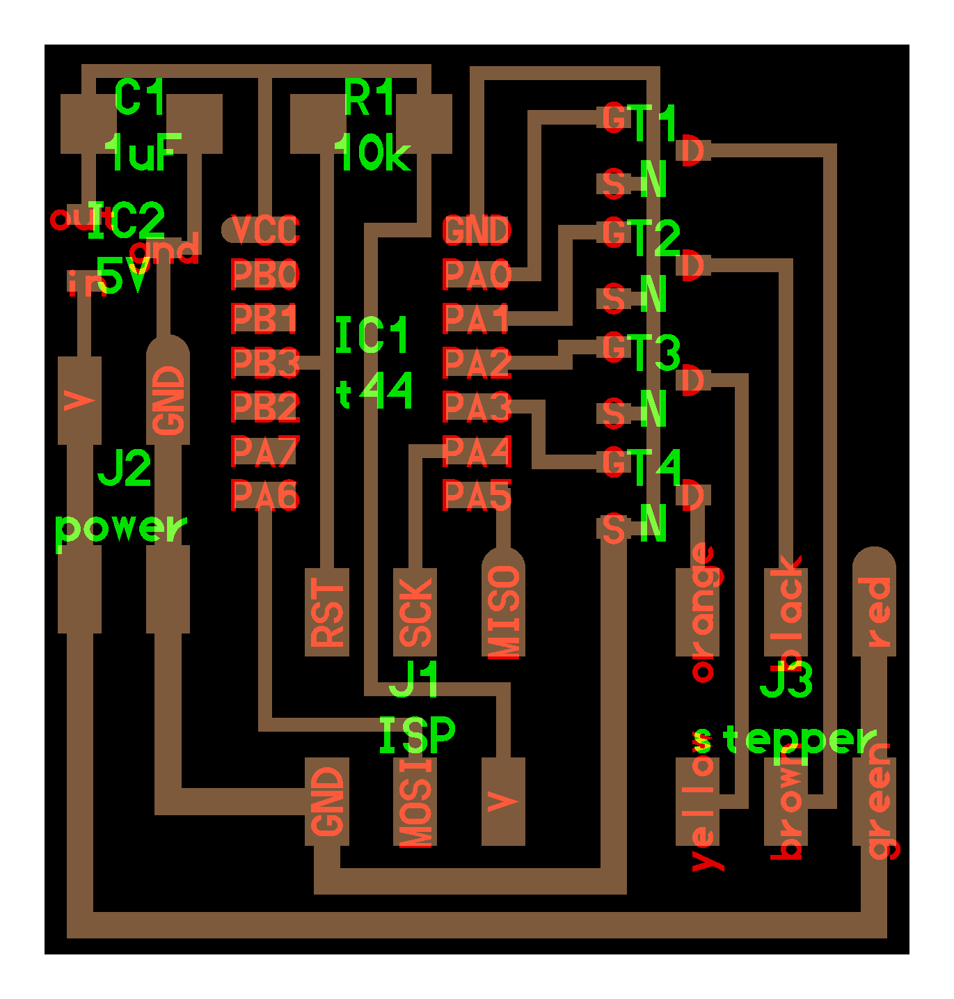
I’ve designed the following PCB board in order to interconnect and control the components mentioned above:

Among the most important components of this board, we can mention the following:
- Microcontroller: ATmega 328p
- Unipolar stepper motor: 4 NMOSFETs for controlling the unipolar stepper motor and a 6 Positions Header Connector for connecting to it.
- Power: A 4 Positions Header Connector and a 5V Voltage regulator
- Networking: A 4 Positions Header Connector for HC-06 bluetooth module
- Extras: A 4 Positions Header Connector for a possible hall effect sensor (not used) and an extra 4 Positions Header Connector exposing unused microcontroller pins.
- Programming: A 6 Positions Header Connector for AVR-ISP connection.
The schematic also includes a footprint for a resonator, but I ended up using the board without it because it was not necessary.

Most parts of the main board design is based on Neil’s hello.stepper.44 board and on Xinhui Hu’s Board. In fact, the 4 Positions Header Connector for hall effect sensor was based on Xinhui Hu’s board. He used this sensor for setting the zero point of the motor moving path. Initially I planned to include the same functionality but I removed from the first iteration because more time is required for testing it.
Power Board
I also decided to place the DC power jack in an independent board to reduce the size of the main board:


Both boards communicate with each other via cables and Receptacle Connectors.
Fabrication
In previous section I explained the processes involved in designing both the external case and the electronics part. Now it’s time to fabricate these designs.
3D Printing
Let’s start with 3D printed components. As I mentioned above, the 3 components that I want to print are the base, the backface and the clockhand. So, I exported the corresponding STLs and opened them on Flashprint.

I added supports to the base because of the platform for the stepper motor. I rotated the backface model and addded supports to the hole I left for the DC jack.

The material I chose for all the components is PLA+ and the parameters I used were the following:
- Material: PLA+
- Layer height: 0.18
- Minimum speed: 60mm/s
- Extruder temperature: 210°C
- Platform temp.: 50°C
- Infill: 75%
- Raft: No
Then I generated .gx files for each model and loaded them into the 3d printers to start the fabrication process:
The base and clockhand components took around 5 hours each one to print. On the other hand, the clockhand took only a few minutes. The results are shown below:


Additionally, I designed one more component to be used as a top frame for the clockface:
I followed the same steps for printing this component and it took around half an hour to finish.

Laser cutting
Now it’s time to use the laser cutter. The components that I need to cut are the sidewalls and the clockface. Let’s start with the clockface:

I exported a DXF file from the fusion 360 sketch I created in the 3D Model shown above. Then I opened Powercut in the laptop connected to the laser cutter and loaded the DXF file. First I selected the letters and lines of the clockface and set the following parameters:
- Power: 15% - 20%
- Speed: 200 mm/s
Then I placed the 3mm MDF sheet into the laser cutter, set the origin and started to draw the lines:
Then I selected the borders and the inner circle, set these values and started cutting:
- Power: 80%
- Speed: 10 mm/s
Finally, here are the results:

Now, let’s continue with the sidewalls. I made some modifications to the sidewall sketch in Fusion360 in order to cover some more areas.

Since this time I used acrylic instead of MDF I had to set the following parameters:
- Power: 85%
- Speed: 15 mm/s

Then I placed the acrylic sheet on the laser cutter and started cutting
Finally, here are the results for the sidewalls:

Electronics production
Now it is time to fabricate the designs presented in the Electronics Design section. In order to do that, I generated gerber files from those designs, imported them into Flatcam and generated the corresponding gcodes to send them to the Roland MODELA PRO II MDX-540 that we have in our lab.

I used the 1/64 inch endmill for the traces and the 1/32 endmil for the cutout, as usual. Then I proceeded to solder the components into the main board:

After soldering all the components the board ended up like this:

To test the board I loaded a simple “blink” program and it worked. I’ll explain how to program boards using the ATmega 328p in future sections:
Then I repeated the same process for fabricating the power board. Here I imported the gerber file into Flatcam and generated a gcode file to mill the board:

Then I proceeded to solder the only two components on this board:

It wasn’t clear for me how to solder the DC jack component. Luckily, Abdón managed to give me a hand with this remotely .

It turned out that the legs connected to the barrel corresponds to VCC and the other two legs are GND.
Packaging
Now that we have all the components, the next step is to integrate them. I started shortening the wires of the components to avoid the unwanted tangling of wires. In order to do that, I used some pliers to cut the wires and then added Receptacle Connectors.

I shortened the following connections using this technique:
- Main board > Stepper motor
- Main board > Bluetooth
- Power Board > Main board
Here is the Fabulous Notifier after placing the electronic components on the 3D printed parts:

And here is the Fabulous Notifier completely assembled:

Embedded programming
In previous sections I listed the electronic components needed to fulfill all the requirements of the Fabulous Notifier Hardware. I also showed how they are connected to the main PCB board. Now it is time to show how the main PCB board is programmed for interacting with all these components.
Microcontroller
As mentioned above, the ATmega328P microcontroller is used on this board. I’ve been using only ATtiny microcontrollers so far, so it is the first time I use the ATmega328P. There are a few differences when programming it and I’ll describe them in this section.
In the first place, there’s a package called Minicore which can be used for programming ATmega328p boards in the Arduino IDE. To install it you have to go to File > Preferences and paste the following link in the Additional Boards Manager URLs field:
https://mcudude.github.io/MiniCore/package_MCUdude_MiniCore_index.json
Then, go to Tools > Board > Boards Manager and install the Minicore package. Once installed, the tools section should look like this:

For programming this board the ATmega328p variant should be selected. Also make sure that the Clock: "Internal 1 MHz" and the Bootloader: "No bootloader" options are selected.
Now let’s talk about the pins used in this project. The pinout of this microcontroller is shown below:

-
Used pins:
-
Programming: 11(MOSI), 12(MISO), 13(SCK), 22(RESET)
- Stepper motor: A0(BLUE), A1(BLACK), A2(RED), A3(YELLOW)
-
Networking: 0(RXD), 1(TXD)
-
Extra pins:
- LED (Not used): 3
- Hall Effect (Not used): 9, 10
- Extra header connector(Not used): 8, 7, 6, 5
- Resonator (Not used): 20(XTAL1), 21(XTAL2)
So, for configuring the used pins, the embedded code starts like this:
...
const int T1_YELLOW = A3;
const int T2_RED = A2;
const int T3_BLACK = A1;
const int T4_BLUE = A0;

void setup()
{
  pinMode(T4_BLUE, OUTPUT);
  pinMode(T3_BLACK, OUTPUT);
  pinMode(T2_RED, OUTPUT);
  pinMode(T1_YELLOW, OUTPUT);
  Serial.begin(9600);
}

...
Bluetooth module
The bluetooth listener is pretty simple to implement using the Serial library. The following piece of code basically waits until some data is received, transforms it to an integer and pass it as an argument to other functions.
...
void loop()
{

  if (Serial.available())
  {
    // Read the data received via bluetooth,
    // Obtain the new position (angle)
    // and call moveToAngle to start moving the stepper motor
    String data = Serial.readString();
    moveToAngle(data.toInt() % 360);
  }
}
...
Additionally, I used the following piece of code (extracted from makertut’s repo) to change Name and Password of my bluetooth module:
#include <SoftwareSerial.h>
SoftwareSerial hcSerial(10, 11); // RX, TX

String fromPC = "";

void setup() {
  Serial.begin(9600); // hardware serial for the USB-PC
  hcSerial.begin(9600);  // software serial Arduino to HC-06 (9600 is default)

  // print instructions
  Serial.println("HC-06 AT Command Programming");
  Serial.println(" -- Command Reference ---");
  Serial.println("AT (simply checks connection)");
  Serial.println("AT+VERSION (sends the firmware verison)");
  Serial.println("AT+NAMExxxxx (to change name to xxxxx");
  Serial.println("AT+PINnnnn (to change password to 4 digit nnnn");
  Serial.println("AT+BAUDn (to change to baud rate #1");
  Serial.println("  BAUD1 = 1200");
  Serial.println("  BAUD2 = 2400");
  Serial.println("  BAUD3 = 4800");
  Serial.println("  BAUD4 = 9600");
  Serial.println("  BAUD5 = 19200");
  Serial.println("  BAUD6 = 38400");
  Serial.println("  BAUD7 = 57600");
  Serial.println("  BAUD8 = 115200");
}

void loop() {
  // Read from HC-06
  if (hcSerial.available()) {
    while(hcSerial.available()) { // While there is more to be read, keep reading.
      Serial.print((char)hcSerial.read());
      }
  }

  // Read from PC
  if (Serial.available()){
    delay(10); //
    fromPC = (char)Serial.read();


      hcSerial.print(fromPC); // show the HC-06 responce
      Serial.print(fromPC); // echo it back to the PC

  }
}
To configure the bluetooth module, follow these steps:
- Load this code into the main board (or into a arduino UNO).
- Connect the HC-06 module to the board.
- Open the serial monitor and start sending AT commands to configure the module.
Stepper motor
As I previously mentioned, the Jameco unipolar stepper motor is used in this project. According to its datasheet, the sequence for moving the stepper motor is the following:

This suggests that:
- For the first step the YELLOW and BLUE pins should be LOW and the RED and BLACK pins should be HIGH.
- For the second step the YELLOW and BLACK pins should be LOW and the RED and BLUE pins should be HIGH.
- For the third step the RED and BLACK pins should be LOW and the YELLOW and BLUE pins should be HIGH.
- For the fourth step the RED and BLUE pins should be LOW and the YELLOW and BLACK pins should be HIGH.
So it could be implemented as follows:
// Sequence for moving the stepper motor according to Datasheet
void stepMotor(int stepType)
{
  switch (stepType)
  {
  case 0:
    digitalWrite(T1_Yellow, LOW);
    digitalWrite(T2_Red, HIGH);
    digitalWrite(T3_Black, HIGH);
    digitalWrite(T4_Blue, LOW);
    break;

  case 1:
    digitalWrite(T1_Yellow, LOW);
    digitalWrite(T2_Red, HIGH);
    digitalWrite(T3_Black, LOW);
    digitalWrite(T4_Blue, HIGH);
    break;

  case 2:
    digitalWrite(T1_Yellow, HIGH);
    digitalWrite(T2_Red, LOW);
    digitalWrite(T3_Black, LOW);
    digitalWrite(T4_Blue, HIGH);
    break;

  case 3:
    digitalWrite(T1_Yellow, HIGH);
    digitalWrite(T2_Red, LOW);
    digitalWrite(T3_Black, HIGH);
    digitalWrite(T4_Blue, LOW);
    break;
  }
}
However, when I executed this code the stepper motor vibrated but didn’t move anywhere.
Then I checked Xinhui Hu’s implementation:
// Sequence for moving the stepper motor according to Xinhui Hu's implementation
void stepMotor(int stepType)
{
  switch (stepType)
  {
   case 0:
    digitalWrite(T1_Yellow, HIGH);
    digitalWrite(T2_Red, HIGH);
    digitalWrite(T3_Black, LOW);
    digitalWrite(T4_Blue, LOW);
    break;

  case 1:
    digitalWrite(T1_Yellow, LOW);
    digitalWrite(T2_Red, HIGH);
    digitalWrite(T3_Black, HIGH);
    digitalWrite(T4_Blue, LOW);
    break;

  case 2:
    digitalWrite(T1_Yellow, LOW);
    digitalWrite(T2_Red, LOW);
    digitalWrite(T3_Black, HIGH);
    digitalWrite(T4_Blue, HIGH);
    break;

  case 3:
    digitalWrite(T1_Yellow, HIGH);
    digitalWrite(T2_Red, LOW);
    digitalWrite(T3_Black, LOW);
    digitalWrite(T4_Blue, HIGH);
    break;
  }
}
This time, the stepper motor moved according to the instructions I sent. However, after some tests I noticed that the distance between steps were not consistent. Since some steps moved more than others, the accuracy of the notifier was very low.
With the help of our instructor Abdón, we found out the correct sequence is as follows:
// Sequence for moving the stepper motor
void stepMotor(int stepType)
{
  switch (stepType)
  {
    case 0:
      digitalWrite(T1_YELLOW, LOW);
      digitalWrite(T2_RED, HIGH);
      digitalWrite(T3_BLACK, HIGH);
      digitalWrite(T4_BLUE, LOW);
      break;

    case 1:
      digitalWrite(T1_YELLOW, LOW);
      digitalWrite(T2_RED, LOW);
      digitalWrite(T3_BLACK, HIGH);
      digitalWrite(T4_BLUE, HIGH);
      break;

    case 2:
      digitalWrite(T1_YELLOW, HIGH);
      digitalWrite(T2_RED, LOW);
      digitalWrite(T3_BLACK, LOW);
      digitalWrite(T4_BLUE, HIGH);
      break;

    case 3:
      digitalWrite(T1_YELLOW, HIGH);
      digitalWrite(T2_RED, HIGH);
      digitalWrite(T3_BLACK, LOW);
      digitalWrite(T4_BLUE, LOW);
      break;
  }
}
Using this sequence the distance between steps is consistent and the accuracy of the notifier has improved significantly.
Complete source code
In the previous sections I showed how the pins are mapped, how to get data from the bluetooth module and how to move the stepper motor. Now it’s time to integrate all of this. In order to do that, variables for tracking the current position were added (currentStep, currentAngle), as well as functions for updating these values (moveToAngle, angleToStep, step). The complete source code for the PCB board is shown below:
const int T1_YELLOW = A3;
const int T2_RED = A2;
const int T3_BLACK = A1;
const int T4_BLUE = A0;
const int MAX_STEPS = 48;

int currentStep = 0; // Indicates in which step I am (0,47)-> your motor do 48 steps in one rotation
int currentAngle = 0; // Indicates in which angle I am (0 to 360)
int numOfSteps = 0;

#define STEP_DELAY 100

void setup()
{
  pinMode(T4_BLUE, OUTPUT);
  pinMode(T3_BLACK, OUTPUT);
  pinMode(T2_RED, OUTPUT);
  pinMode(T1_YELLOW, OUTPUT);
  Serial.begin(9600);

  currentStep = 0;
  currentAngle = 0;
}


// Sequence for moving the stepper motor
void stepMotor(int stepType)
{
  switch (stepType)
  {
    case 0:
      digitalWrite(T1_YELLOW, LOW);
      digitalWrite(T2_RED, HIGH);
      digitalWrite(T3_BLACK, HIGH);
      digitalWrite(T4_BLUE, LOW);
      break;

    case 1:
      digitalWrite(T1_YELLOW, LOW);
      digitalWrite(T2_RED, LOW);
      digitalWrite(T3_BLACK, HIGH);
      digitalWrite(T4_BLUE, HIGH);
      break;

    case 2:
      digitalWrite(T1_YELLOW, HIGH);
      digitalWrite(T2_RED, LOW);
      digitalWrite(T3_BLACK, LOW);
      digitalWrite(T4_BLUE, HIGH);
      break;

    case 3:
      digitalWrite(T1_YELLOW, HIGH);
      digitalWrite(T2_RED, HIGH);
      digitalWrite(T3_BLACK, LOW);
      digitalWrite(T4_BLUE, LOW);
      break;
  }
}

// Move x steps (negative will move backwards)
void step(int stepsToMove)
{
  int stepsLeft = abs(stepsToMove); // how many steps to take
  int direction = 0;

  // determine direction based on whether stepsToMove is + or -:
  if (stepsToMove > 0)
  {
    direction = 1;
  }

  if (stepsToMove < 0)
  {
    direction = 0;
  }

  // decrement the number of steps, moving one step each time:
  while (stepsLeft > 0)
  {
    // increment or decrement the step number,
    // depending on direction:
    if (direction == 1)
    {
      currentStep++;
      if (currentStep == MAX_STEPS)
      {
        currentStep = 0;
      }
    }
    else // direction==0
    {
      if (currentStep == 0)
      {
        currentStep = MAX_STEPS;
      }
      currentStep--;
    }
    // decrement the steps left:
    stepsLeft--;

    // step the motor to step number 0, 1, ..., {3 or 10}
    stepMotor(currentStep % 4);
    delay(STEP_DELAY);
  }
}

// Obtain the number of steps required for moving x degrees from the current position
int angleToStep(int angle) {
  return (angle * 48) / 360;
}

// Moves the stepper motor to a specific Angle
void moveToAngle(int angle)
{
  // Find the shortest path (meaning, which direction requires the least number of steps)
  int difference = angle - currentAngle;
  if (abs(difference) > 180) {
    int conjugateAngle = 360 - abs(difference);
    numOfSteps = -(difference >= 0 ? -angleToStep(conjugateAngle) : angleToStep(conjugateAngle));
  } else {
    numOfSteps = -(angleToStep(difference));
  }
  currentAngle = angle;
  // Move the stepper motor
  step(numOfSteps);
}


void loop()
{

  if (Serial.available())
  {
    // Read the data received via bluetooth,
    // Obtain the new position (angle)
    // and call moveToAngle to start moving the stepper motor
    String data = Serial.readString();
    moveToAngle(data.toInt() % 360);
  }
}
License
As I mentioned in the Invention, Intellectual Property, and Income week the Fabulous Notifier hardware and embedded code are licensed under Attribution-ShareAlike 4.0 International.

This license requires that reusers give credit to the creator. It allows reusers to distribute, remix, adapt, and build upon the material in any medium or format, even for commercial purposes. If others remix, adapt, or build upon the material, they must license the modified material under identical terms.
Fabulous Notifier Android App
In this section I’ll share details about the decisions that influenced the development process of the Fabulous Notifier App, which is used for comunicating with the Fabulos Notifier device. The source code of the app is available at: https://gitlab.fabcloud.org/academany/fabacademy/2022/students/fabulous-notifier
App development
The app has two main functionalities:
- Connect to bluetooth classic devices.
- Listen to all the notifications received by the user’s smartphone and process some rules to perform actions.
Technologies used
I don’t have much experience developing native apps. But I know how to develop web apps using React and Typescript. Hopefully there’s a framework for building mobile apps using Javascript called Expo.

Expo is an open-source project for building native iOS and Android apps in JavaScript/Typescript. It is built on top of React Native, a popular library that lets you control the native UI components from iOS and Android using JavaScript. It’s a proven technology and many companies are already using in production so that their web developers can be native mobile developers too.
When you’re developing an app with Expo, you don’t need Xcode or Android Studio. All you need is a text editor of your choice and a tool called Expo-cli which runs on Mac, Windows, and Linux. Expo-cli helps you set up new projects, and provides a set of tools to make common tasks like viewing logs and opening the app on your device as they should be. It also lets you share your app while you’re working on it so your coworkers can watch your changes live, and publish your app to Expo servers so it can be accessed at any time. Expo will also build your app binaries for you, so all you need to do is run one command and we will give you the IPA or APK file, ready to submit to the App Stores.

To be able to implement the two main functionalities I mentioned above I need to use the following dependencies:
- react-native-bluetooth-classic: For connecting/interacting with bluetooth classic devices.
- react-native-android-notification-listener: For listening all the notifications on the devices.
Both dependencies depends on native code that is not implemented in the regular Expo development environment. So in order to use these dependencies I also have to use a Custom Development Client. The video below clearly explains what they are:
Additionally, all user data is persisted locally using @react-native-async-storage/async-storage.
To sum up, the following technologies were used for developing the app:
- Typescript
- React Native
- Expo + Custom Development Client
- @react-native-async-storage/async-storage
- react-native-android-notification-listener
- react-native-bluetooth-classic
Key limitation: As its name suggests, react-native-android-notification-listener works only on Android devices. The main reason is that iOS has different privacy rules than Android and it is not possible to access other apps notifications on iOS devices. Since this functionality is important for the Fabulous Notifier app, the app will only be available for Android devices for the moment.
Notification listener implementation
Every Time a notification is received, the following piece of code is executed:
 const headlessNotificationListener = async ({ notification }: any) => {
    /**
     * This notification is a JSON string in the follow format:
     *  {
     *      "app": string,
     *      "title": string,
     *      "titleBig": string,
     *      "text": string,
     *      "subText": string,
     *      "summaryText": string,
     *      "bigText": string,
     *      "audioContentsURI": string,
     *      "imageBackgroundURI": string,
     *      "extraInfoText": string,
     *      "groupedMessages": Array<Object> [
     *          {
     *              "title": string,
     *              "text": string
     *          }
     *      ]
     *  }
     */

    // 1) If notification received
    if (notification) {

        // 2) Parse the notification string
        const parsedNotification =  !!notification ? JSON.parse(notification) : null;

        // 3) Load information about the connected bluetooth device and the notification flows configurations stored in locally.
        const address = await getString('device');
        const flows = await getData('flows');

        // 4) Store the received notification
        await AsyncStorage.setItem('@lastNotification', notification)


        // 5) Check if there's a notification flow related to the received notification.
        const found = flows?.find(x => parsedNotification?.app?.toUpperCase()?.includes(x.name?.toUpperCase()));

        // 6) If there's a bluetooth device connected.
        if(address){

            // 7) Load the rules related to the notification flow
            const rules = await getData(`${found?.name}-rules`);

            // 8) Check if the current notification's keyword matches one of the rules.
            const ruleFound = rules?.find(x => {
                const keyword = x?.keyword?.toUpperCase();

                return ((parsedNotification?.groupedMessages && parsedNotification?.groupedMessages?.length > 0 && parsedNotification?.groupedMessages?.[parsedNotification?.groupedMessages?.length - 1]?.text?.toUpperCase()?.includes(keyword)) || parsedNotification?.title?.toUpperCase()?.includes(keyword) || parsedNotification?.titleBig?.toUpperCase()?.includes(keyword) ||
                    parsedNotification?.text?.toUpperCase()?.includes(keyword) || parsedNotification?.subText?.toUpperCase()?.includes(keyword) ||
                        parsedNotification?.summaryText?.toUpperCase()?.includes(keyword) || parsedNotification?.bigText?.toUpperCase()?.includes(keyword) );


            });

            // 9) If rule matched, Send the value associated to the rule to the connected device
            if(ruleFound){
                await RNBluetoothClassic.writeToDevice(address, `${ruleFound?.value}\r`);
            }
        }
    }
}
- If notification received
- Parse the notification string
- Load information about the connected bluetooth device and the notification flows configurations stored in locally.
- Store the received notification
- Check if there’s a notification flow related to the received notification.
- If there’s a bluetooth device connected.
- Load the rules related to the notification flow
- Check if the current notification’s keyword matches one of the rules.
- If rule matched, Send the value associated to the rule to the connected device
Using the app
In this section I will show how to use the Fabulous Notifier app. The app is not available at the google store, but it can be installed in two different ways:
Once the app is installed and opened, the spash screen with the “Fabulous Notifier” logo and the main screen will be shown.

The main screen shows a bottom bar with two tabs:
- Notifications: For configuring notification tracking.
- Devices: For managing bluetooth connections.
When the “Devices” tab is opened, a list of bonded devices will appear. To scan more devices, the scan button can be pressed.

The Fabulous Notifier’s bluetooth name is “Fabulous Notifier”, to connect to this device the corresponing card must be selected. If everything goes well, the “Connection succesful” message will appear.
Now let’s move to the “Notifications” bottom tab to start configuring notification flows. The main page will show a list of configured notification flows, let’s press the “Add flow” option to add a new one. Then a list of supported apps will appear and one of them should be selected to continue.

Once an app is selected, the rules associated to that app will appear. Rules consists in Keyword/Value pairs for an specific App. For instance, if the app selected is Calendar and there is a rule with Keyword/phrase=”Important meeting” and value=”180” every time the smartphone receives a notification from Google Calendar that contains “Important meeting” in its body, the value “180” will be sent to the connected device. When the Fabulous Notifier receives that value, the clock hand will move to the 180ª angle.
License
I chose the MIT license for the Fabulous Notifier Android App, which is a pretty straightforward, clear and permissive license. Other users can commercialize, distribute, modify and use. The only requirement is to preserve the copyright and license notices. Most of the dependencies in this project are licensed under this license so I chose the same one for consistency and simplicity.

Testing & Evaluation
During the Applications and Implications week I defined these evaluation points:
- The app starts successfully.
- The user can configure flows using the app.
- The app successfully connects to the device .
- The device executes the configured flows.
The first theree points were achieved in the Fabulous Notifier Android App > Using the app section of this page where I showed how to open the app and how to configure different flows. If you want to want to see how these poins were achieved please watch the video I added to that section.
In this section I will show how the last point is achieved. To see how the device executes the configured flows, please watch the following video:
Bill of Materials
Electronics
Main Board (~ $11.55)
| Part | Value | Device | Package | Code | Price |
| BACKUP | PINHD-2X2-SMD | PINHD-2X2-SMD | 2X02SMD | 609-5160-1-ND | $0.97 |
| C1 | 1uF | CAP-UNPOLARIZED | C1206 | 399-4674-1-ND | $0.35 |
| HALL | PINHD-2X2-SMD | PINHD-2X2-SMD | 2X02SMD | 609-5160-1-ND | $0.97 |
| HC-06 | PINHD-2X2-SMD | PINHD-2X2-SMD | 2X02SMD | 609-5160-1-ND | $0.97 |
| IC1 | ATMEGA328P-AU | ATMEGA328P-AU | TQFP32-08THIN | ATMEGA328P-AU-ND | $2.86 |
| POWER | PINHD-2X2-SMD | PINHD-2X2-SMD | 2X02SMD | 609-5160-1-ND | $0.97 |
| R1 | 10k | RES-US1206 | R1206 | 311-10.0KFRCT-ND | $0.10 |
| R2 | 0 | RES-US1206 | R1206 | 311-0.0ERCT-ND | $0.10 |
| R3 | 499 | RES-US1206 | R1206 | 311-499FRCT-ND | $0.10 |
| R4 | 0 | RES-US1206 | R1206 | 311-0.0ERCT-ND | $0.10 |
| STEPPER | PINHD-2X3-SMD | 2X03SMD | 609-5161-1-ND | $1.02 | |
| T1 | NMOSFETSOT23 | SOT-23 | MOSFET N-CH SSOT3 | $0.26 | |
| T2 | NMOSFETSOT23 | SOT-23 | MOSFET N-CH SSOT3 | $0.26 | |
| T3 | NMOSFETSOT23 | SOT-23 | MOSFET N-CH SSOT3 | $0.26 | |
| T4 | NMOSFETSOT23 | SOT-23 | MOSFET N-CH SSOT3 | $0.26 | |
| U$1 | AVRISPSMD | AVRISPSMD | 2X03SMD | 609-5161-1-ND | $1.02 |
| U$2 | LED | LED | LED1206 | 160-1169-1-ND | $0.31 |
| U2 | NCP1117ST50T3G | NCP1117ST50T3G | SOT230P700X180-4N | NCP1117ST50T3G | $0.67 |
Power Board (~ $2.42)
| Part | Value | Device | Package | Code | Price |
| J1 | PJ-002AH-SMT-TR | PJ-002AH-SMT-TR | PJ-002AH-SMT-TR_CUD | CP-002AHPJCT-ND | $1.45 |
| U$1 | PINHD-2X2-SMD | PINHD-2X2-SMD | 2X02SMD | 609-5160-1-ND | $0.97 |
Modules (~ $18.95)
- HC-06 Bluetooth module: $10
- Jameco Unipolar Stepper Motor Step 7 Volt DC-350 mA 7.5 Step Angle 680 G-CM: $8.95
Materials (~ $49)
- PLA Spool, 1kg: $25
- 15cm x 15cm Copper plate: $4
- 3mm Acrylic sheet: $10 approx.
- 3mm MDF sheet: $10 approx.
Approx Total for fabricating the Fabulous Notifier: $81.92
Files
Electronics design:
Programming:
3D design:
STL files for 3D printing:
DXF files for laser cutting:
2D design: