CHECK LIST
Group assignment
- compare the performance and development workflows for other architectures
Embedded System
An embedded system is a microprocessor-based computer hardware system with software that is designed to perform a dedicated function, either as an independent system or as a part of a large system. At the core is an integrated circuit designed to carry out computation for real-time operations.
Complexities range from a single microcontroller to a suite of processors with connected peripherals and networks; from no user interface to complex graphical user interfaces. The complexity of an embedded system varies significantly depending on the task for which it is designed.
Microprocessor VS Microcontrollers
What is Microcontroller?
A microcontroller is a chip optimized to control electronic devices. It is stored in a single integrated circuit which is dedicated to performing a particular task and execute one specific application. It is specially designed circuits for embedded applications and is widely used in automatically controlled electronic devices. It contains memory, processor, and programmable I/O.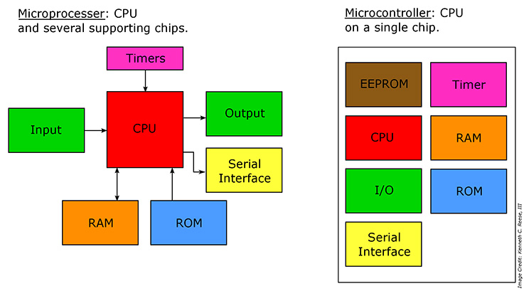
What is a Microprocessor?
A microprocessor is a controlling unit of a micro-computer wrapped inside a small chip. It performs Arithmetic Logical Unit (ALU) operations and communicates with the other devices connected with it. It is a single Integrated Circuit in which several functions are combined.
|
Types of Microprocessor
Important types of Microprocessors are:
- Complex Instruction Set Microprocessors
- Reduced Instruction Set Microprocessors
- Digital Signal Multiprocessors (DSPs)
- Types of Microcontroller
Here are important types of Microcontroller
- 8 bit Microcontroller
- 16 bit Microcontroller
- 32 bit Microcontroller
- Embedded Microcontroller
- External memory Microcontroller
PROGRAMMING THE ATTINY 1614
Download and install Arduino IDE
from this site.
The Arduino Software (IDE) allows to write programs and upload them to the board.
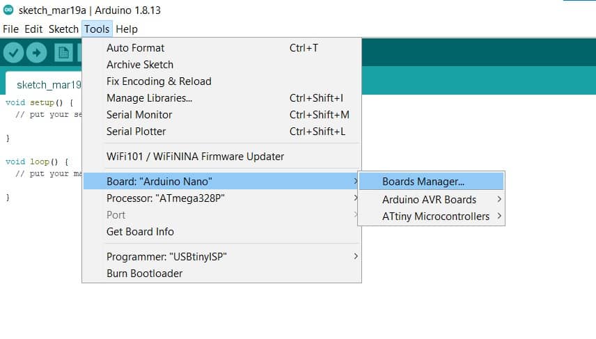
In order for Arduino IDE to recognize a board connected to the PC, it is required to install the
corresponding core for that board's microprocessor. This way, when the board is plugged in, Arduino IDE
will detect it and the corresponding port will show under Tools > Port ready to be selected.
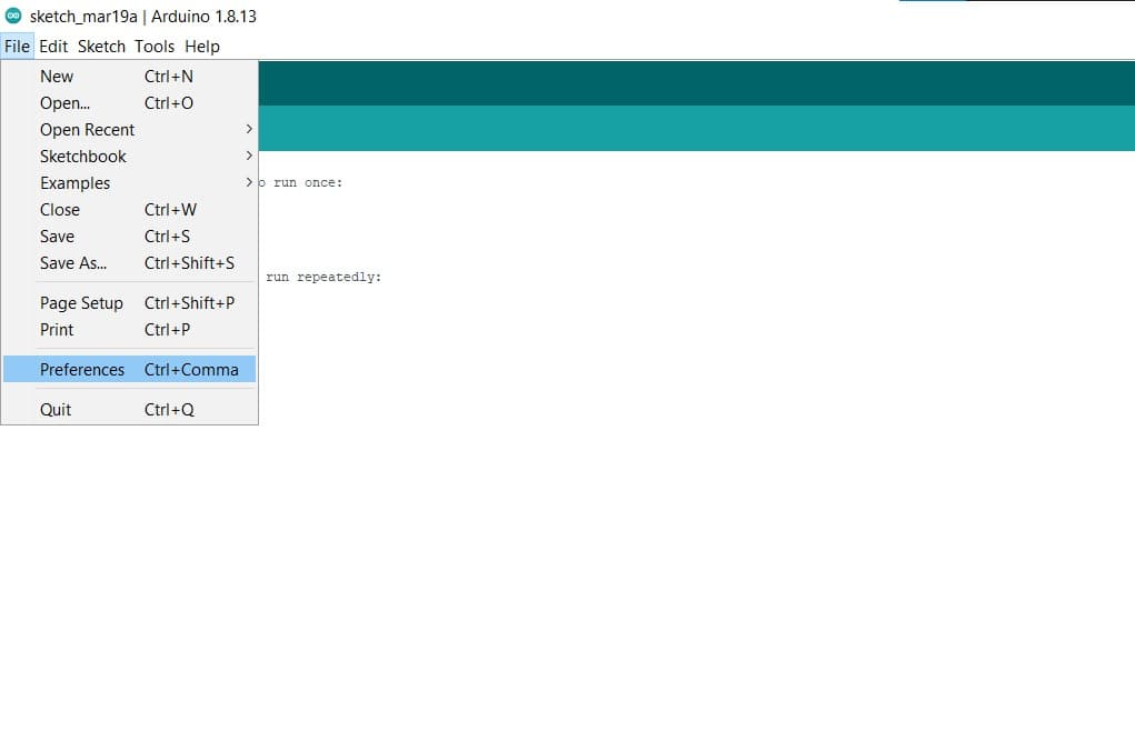
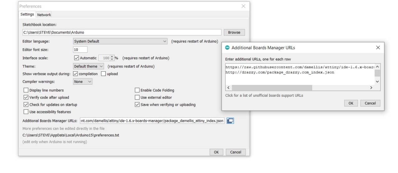
We used a 3rd party hardware package, so it is first necessary to add the URL of their Boards Manager
JSON file in: File > Preferences > Additional Boards Manager URLs. The URLs point to JSON index files
that Arduino IDE uses to build the list of available installed boards.
The following site shows step by step how to Make the UPDI Programmer to be able to upload code to the attiny series using the IDE and an Arduino board. Click here
To transform the Arduino board to a UPDI programmer, we will use the UPDI Arduino sketch created by ElTangas. The sketch converts ATmega328(p)-based Arduino’s, like the Arduino UNO, Nano, and Pro mini, into a UPDI programmer.
There are two steps to do this. The first step involves transforming an Arduino board to serve as the UPDI programmer while the second part shows how to connect the Attiny to the programmer and the Upload process.
1. Transform an Arduino to a UPDI programmer
- Close all instances of the Arduino IDE to avoid errors.
- Download and extract the UPDI programmer sketch
- Open the jtag2updi folder after extracting the download. It is important that all the files extracted to be in the same folder.

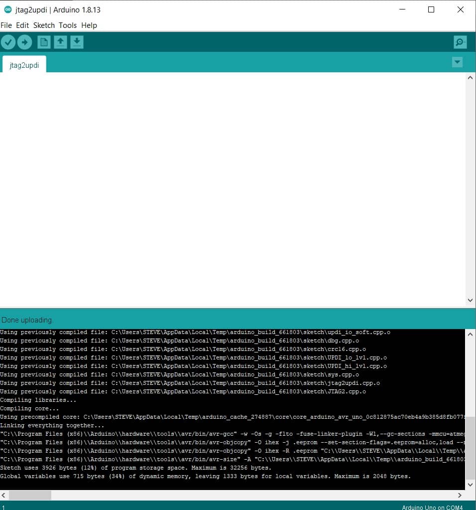
- Open the sketch jtag2updi.ino and upload it to the Arduino board you will like to use (in this case Arduino UNO).
When you open the code, the .ino file will appear empty and that is fine as all the code is contained in the other files
in the same folder as the .ino, but the empty .ino is needed so they can be compiled by the IDE.
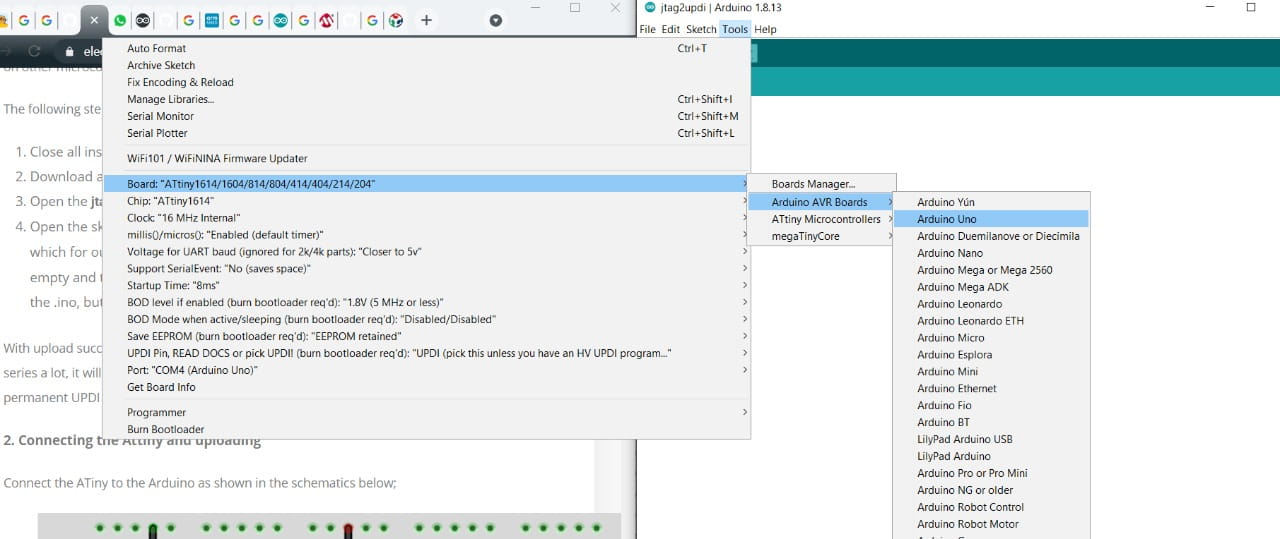
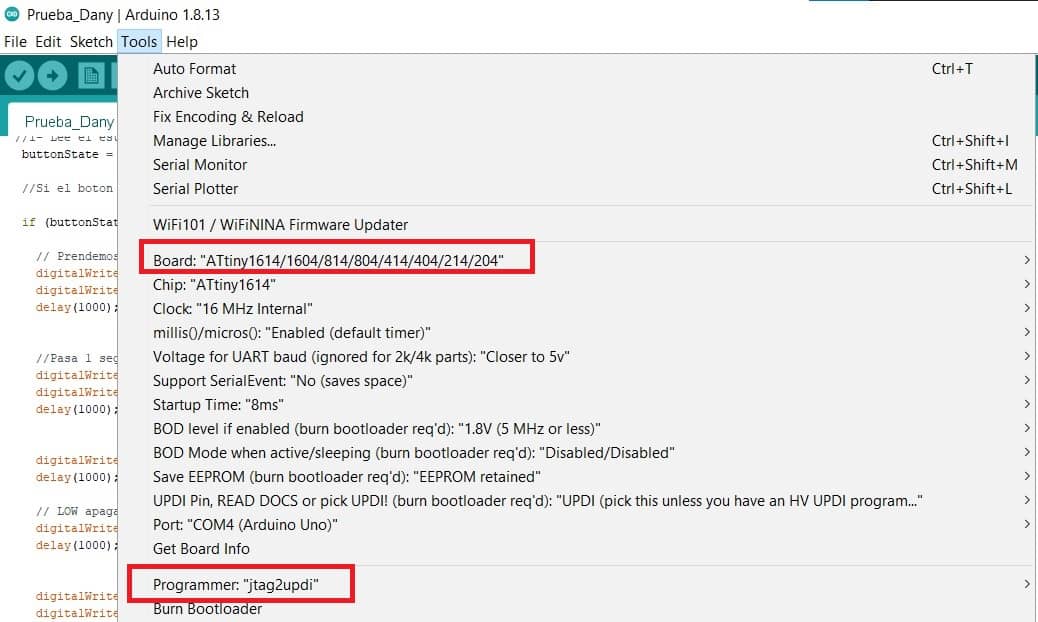
- Tools> Board > Arduino AVR boards> Arduino Uno
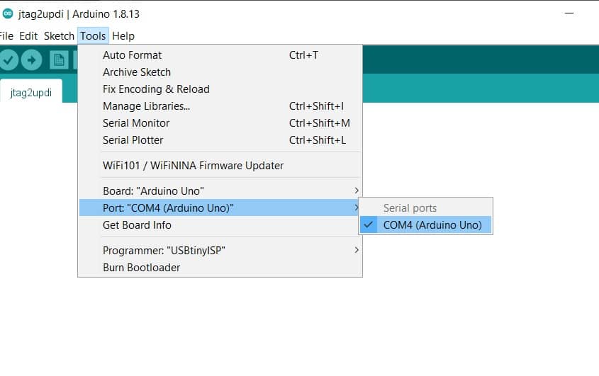
- Tools> Port> COM4 (Arduino uno)
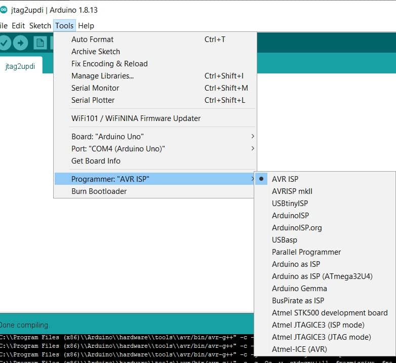
- Tools> Programmer AVR ISP>AVR ISP
- Tools> Programmer jtag2updi> jtag2updi
2. Connecting the Attiny and uploading
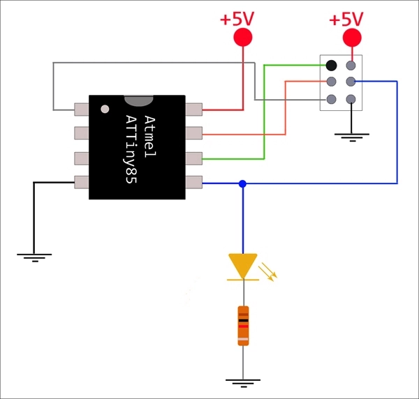
Connect the ATiny to the Arduino as shown in the schematics below:
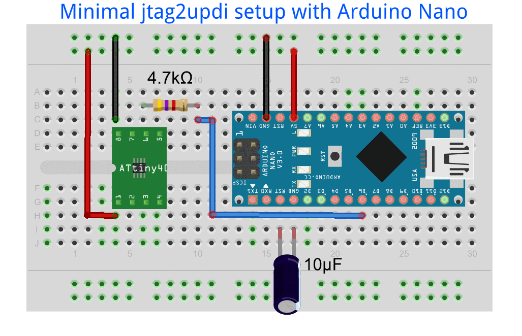
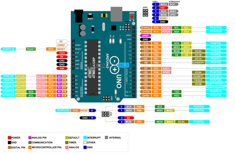
It is important to be aware of the Arduino Uno pinout as well as the attiny, so in order to prevent mistakes this is the
pin (Arduino) to pin (Attiny) connection:
| Arduino | Attiny |
|---|---|
| GND | GND |
| 5V | VCC |
| D6 | UPDI |
Also add:
- 4.7Ω resistance
- 10uf capacitor
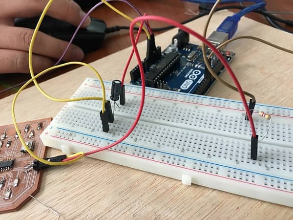
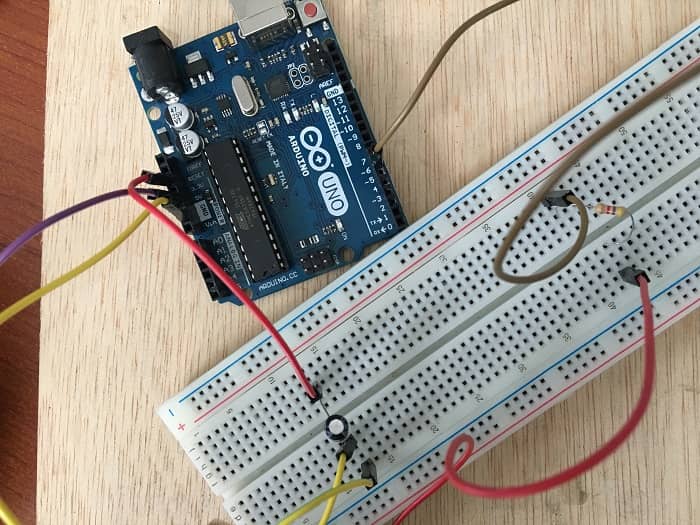
This is the result so far,
CODE THE ATTINY
Open or write the code you would like to upload.For this exercise I used the code provided by Adrian on this
week, which is avaliable Here
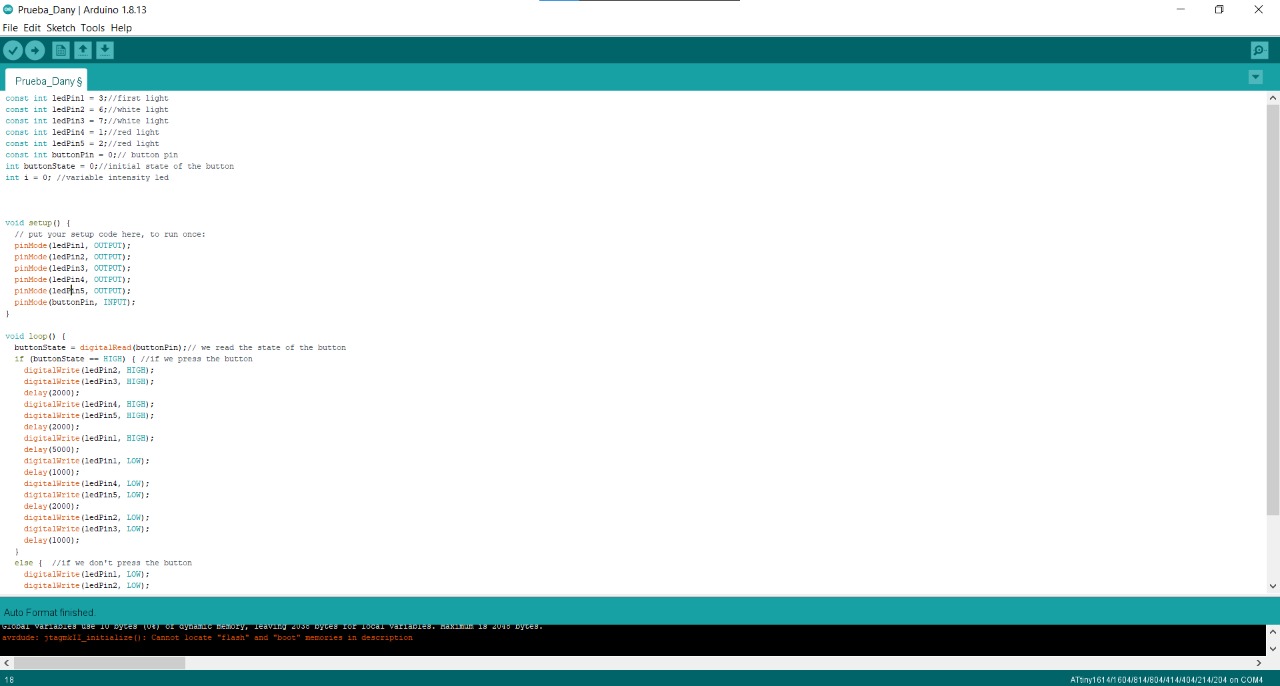
This was the result:
From Adrian's code I changed some information, for example white leds weren't avaliable at the lab so
I placed blue ones, and also changed the time between them turning on. This was the final code I used:
//Daniela Felix - Fab Academy 2021 - Fab Lab ZOI
//tiny1614
//
//Original code:Neil Gershenfeld 12/8/19
// This work may be reproduced, modified, distributed,
// performed, and displayed for any purpose, but must
// acknowledge this project. Copyright is retained and
// must be preserved. The work is provided as is; no
// warranty is provided, and users accept all liability.
//
const int ledPin1 = 3;//first light
const int ledPin2 = 6;//white light
const int ledPin3 = 7;//white light
const int ledPin4 = 1;//red light
const int ledPin5 = 2;//red light
const int buttonPin = 0;// button pin
int buttonState = 0;//initial state of the button
int i = 0; //variable intensity led

void setup() { //declaration of inputs and outputs
pinMode(ledPin1, OUTPUT);
pinMode(ledPin2, OUTPUT);
pinMode(ledPin3, OUTPUT);
pinMode(ledPin4, OUTPUT);
pinMode(ledPin5, OUTPUT);
pinMode(buttonPin, INPUT);
}
void loop() {
buttonState = digitalRead(buttonPin);// we read the state of the button
if (buttonState == HIGH) { //if we press the button
digitalWrite(ledPin2, HIGH);
digitalWrite(ledPin3, HIGH);
delay(2000);
digitalWrite(ledPin4, HIGH);
digitalWrite(ledPin5, HIGH);
delay(2000);
digitalWrite(ledPin1, HIGH);
delay(5000);
digitalWrite(ledPin1, LOW);
delay(1000);
digitalWrite(ledPin4, LOW);
digitalWrite(ledPin5, LOW);
delay(2000);
digitalWrite(ledPin2, LOW);
digitalWrite(ledPin3, LOW);
delay(1000);

}
else {  //if we don't press the button
digitalWrite(ledPin1, LOW);
digitalWrite(ledPin2, LOW);
digitalWrite(ledPin3, LOW);
digitalWrite(ledPin4, LOW);
digitalWrite(ledPin5, LOW);
}
}
This was the result:
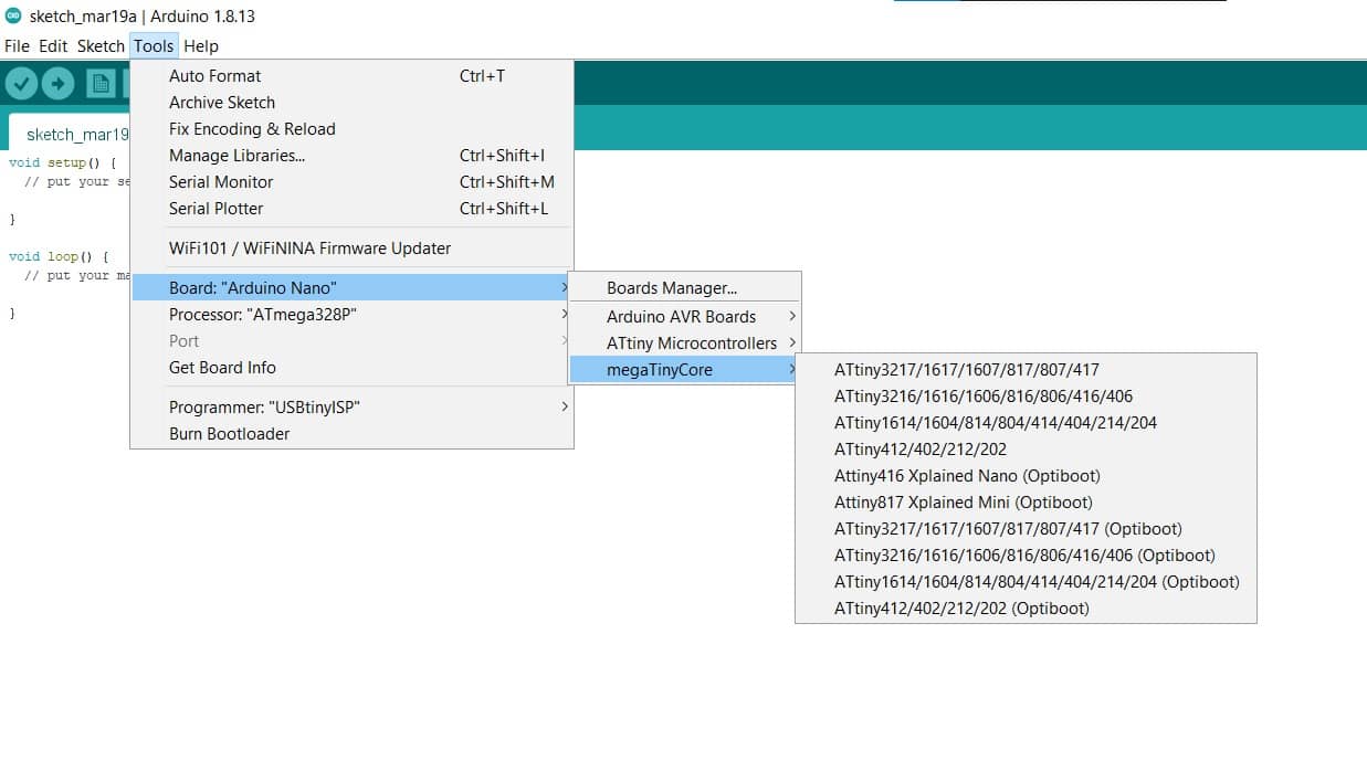
Verify the code to ensure that there is no error, then go to Tools> Board, and scroll down till you see the ATtiny you are working with on the list and select it.
PROGRAMMING THE ATTINY 44A
I put two leds in this board to make a blinking led while the other can be activated pressing the button. To program the ATtiny44 I use the USBtinyprogrammer did it in week 4 and Arduino IDE. The following information are the steps to do it.
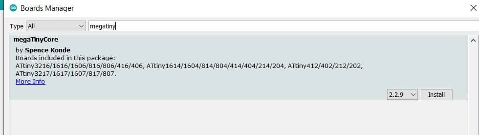
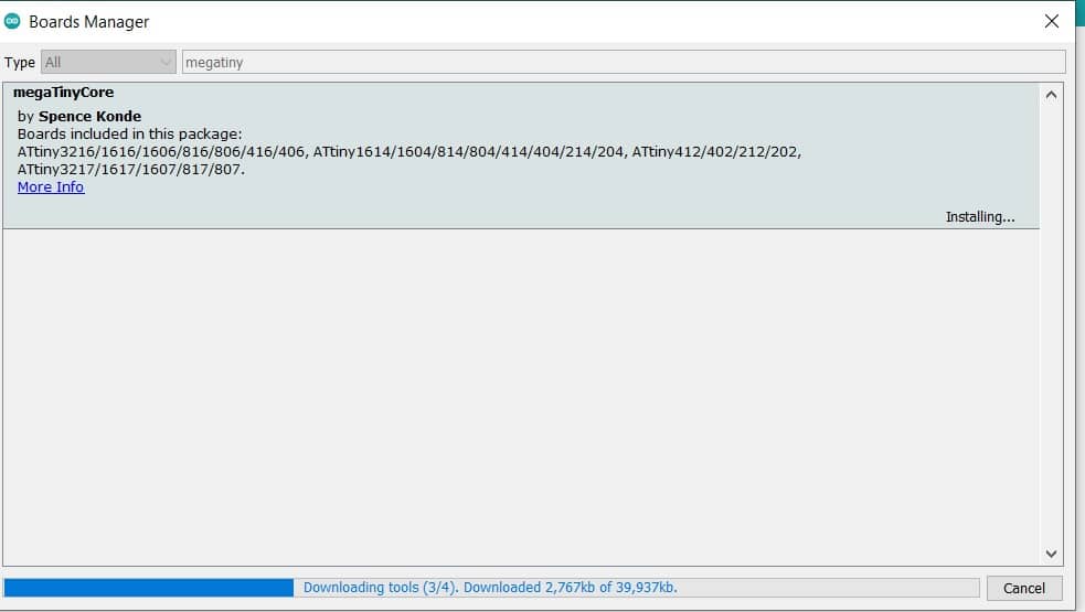
An important thing to know is that I did not need to upload the bootloader to upload the code to the HelloWorld board so I will skip this part. First you have to download the ATtiny Microcontrollers library, to do it use this link where you will find the libraries and the instructions to do it.
Once you have the configuration as the image above, please notice that the clock you use depends on two things:
- If you have an external crystal/ceramic resonator.
- If you have burn the fuses to use an external crystal/ceramic resonator.
So if you haven't burn the fuses that means that you are using the internal resonator. I notice this because the blinking timing was not the expecting miliseconds and also because the serial comunnication was not right. Be sure you are setting the right clock in arduino IDE to make things work as expected.
So then you should press the upload button and after waiting some time have the code upload to your board, if you have an error message you have to find wich element it's caussing the problem. I recomend to check some things:
- Firts check the setting in Arduino IDE are correct, the PORT where your programmer is connected have to be selected
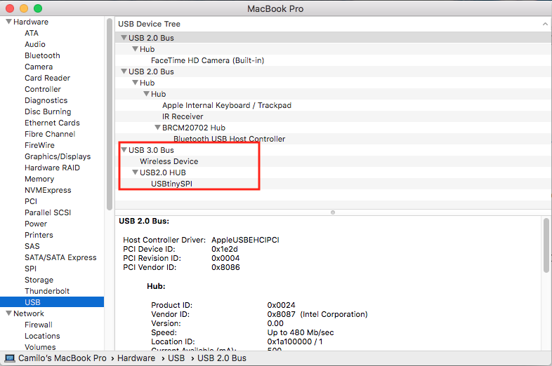
- mac OS users should also verify if the device is being reconized clicking on About this mac --> System Report
- Be sure the programmer works well, even a loose USB connection can cause the problem.
- Verify the ISP connection is correct.
- Verify the cables you are using are good.
- Check your board, this include soldering, right design, right components, continuity and so on.
- Try to discard items so you reduce the possible problems list.
- If you are sure you can program other board with the same programmer and the same enviorment and also check your board and think it's okay you should replace your micro, it could be setting wrong fuses and now it's not enable to communicate anymore until you do a fuse reset.
The program I did is a Blink wothout delay. The delay instruction make the microcontroller stop "thinking" while the delay time is going on. That means it can't perform any other action as read sensors, communicate or anything. For this reason you can use this code that replace the delay() and allows the micro keep working on other instructions. In this case I use a blinking LED and whe you press the button another led turns on, but also I decide to try the serial communication in the same code.
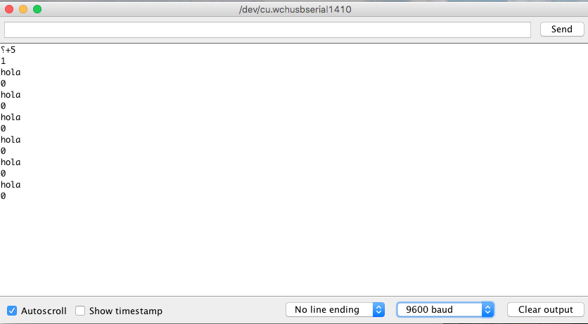
Now on purpose of serial communication. This is how it looks when the baud rate/ clock setting is not correct.
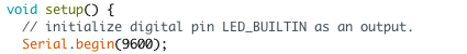
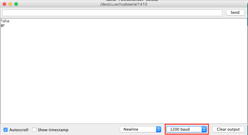
As you can see the baud rate on Serial.begin it's not the same as the Serial Monitor on Arduino IDE but it should be, also the symbols are not correct. Here is where I read the clock information in the datasheet I wrote before in this page. So changing the clock to: 1Mhz internal clock in arduino IDE it kind of work but still with problems.
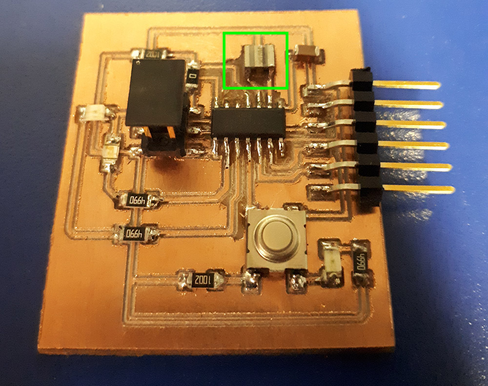
Here I decide to burn the fuses to use the external 20Mhz ceramic oscilator integrated in my board.
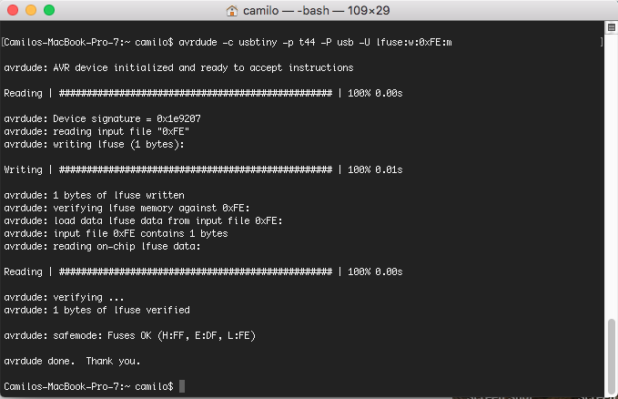
Then try again the communication. Change in Arduino IDE to external 20Mhz clock upload the program and check.
The communication are being stablished in the corect baud rate, in the first line there is some noise, that noise could be cause because I'm usig the arduino as a bridge to connect with serial to the computer, that is not the problem, the problem could be the horrible cables in the connection.
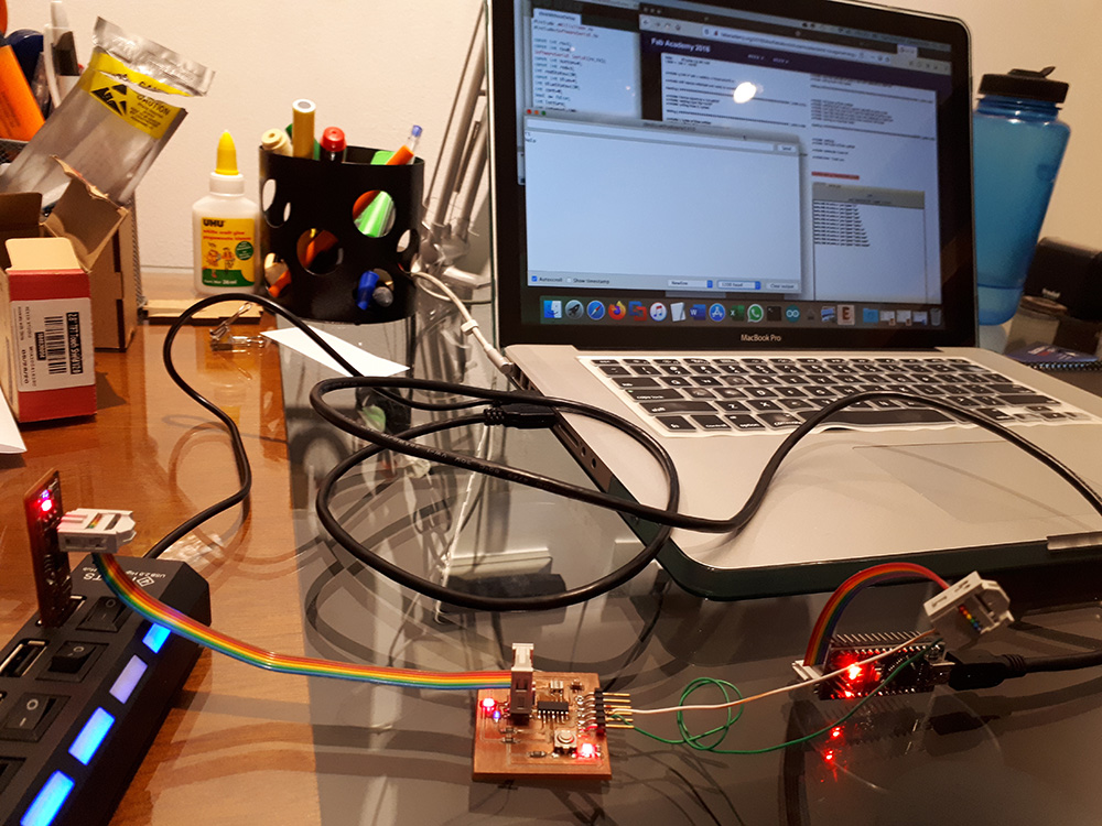
This time I didn't have female wires so I have to use that wires and I think that can be the problem.
Hello World Results
This example can be very usefull on a lot of projects, you can learn more obout it searching the explanation of the blinking without delay to more details, and of course you will find the original files at the end of this page.
Original Files
PROGRAMMING THE ATTINY45
Using the Arduino IDE
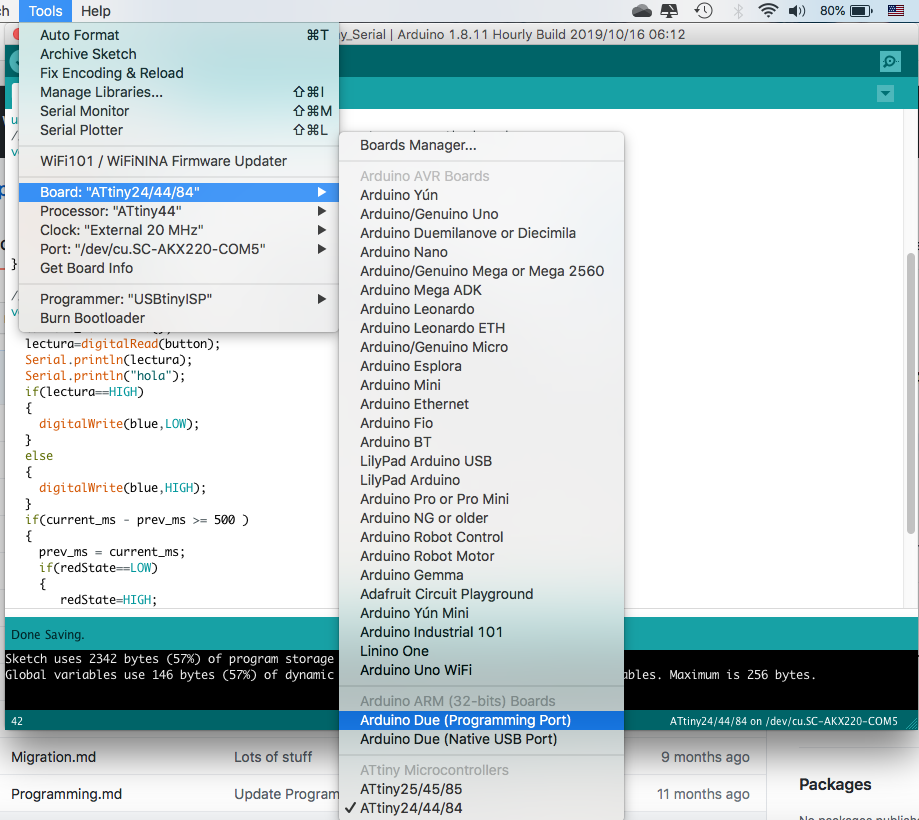
To program the ATtiny45 chip with the Arduino IDE is important to install the ATtinyCORE, you can follow this tutorial page to install it. After that you should set the settings as shown on the next image.
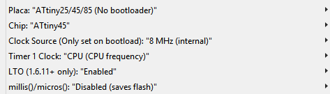
Using this environment to develop is pretty straight forward. The main things are to set the appropriate board and clock settings from the tools>board menu, and then tools>chip, is also important to enable the LTO that makes the complied program smaller tools>LTO>enable
Then you write your program as any other Arduino program, be aware that some functions will not work and also you have less flash and RAM memory to work with.
Compile your program and set your programmer inside the tools>programmer>USBtinyISP menu, make sure your programmer and board are connected, and finally upload your sketch to your microcontroller.
Programming with PlatformIO
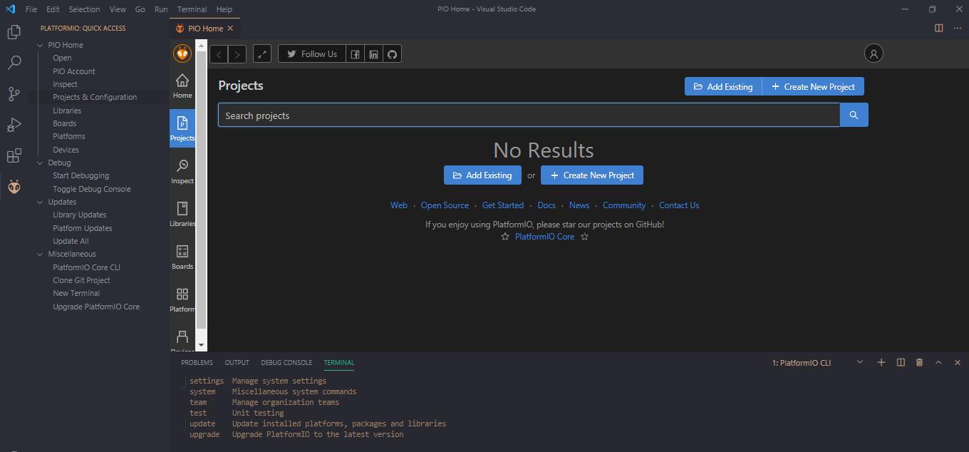
PlatformIO can be installed via a VS code extension, then you can enjoy the benefits of using PlatformIO while having the power of VS code
Also, as VS code is more powerful you will get intellisense and code auto completion. Which is always nice and handy, to install it you must go to the extension tab and search for PlatformIO click on install.
You will have now an icon for the PlatformIO home, where you can create new project or import form the Arduino IDE. When creating the project you should select which chip you will be targeting and a root folder. In this case the ATtiny45.
On the project a file named main.cpp will be created, there you should put your code. You can write normal Arduino Code and C code. To compile and upload you can use the buttons that will be added to the bottom bar or the following commands:
- ctrl+alt+b / cmd-shift-b Build Project
- ctrl+alt+u Upload Firmware
- ctrl+alt+s Open Serial Port Monitor
Make sure your programmer is connected to the computer and the board
Using C files
You can use plain C to program you AVR chip, then use the AVR Toolchain to compile it and generate a .hex file. That you finally upload using avrdude. To edit the code I use VS code, but you can use any editor.
Using Makefiles!
With this type of files used with the GNU make program you can automate a lot of the compile and uploading tasks of your project. I found this great tutorial that makes a step by step breakdown of the Makefile and how it works.
target: prerequisites
                            recipe
The example above is a basic format for a make rule, you can chain this based on how to make the prerequisites.
PROJECT=main.lightsensor

                        $(PROJECT).hex
You can also declare variables, on the previous example the project variable is used to name a file .hex with the variable value.
Is also a good practice to make a clean: recipe that will delete all the generated files and leave the directory clean