OUTPUT DEVICES
This week I learned about output devices and how to program them.
Group Work
In the Thursday lab, Professor Goodman introduced us to a variety of different output devices, including motors. My group hooked up a DC motor to a battery pack and measured its current and voltage. We used two multimeters to do this. One wired into the circuit to measure current and the other set to measure voltage drop around the motor.
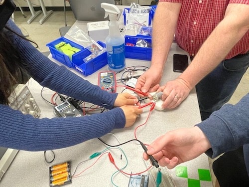
We found that when someone tried to hold the shaft to stop it from moving the voltage went down and the amperage increased.
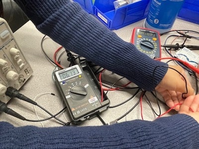
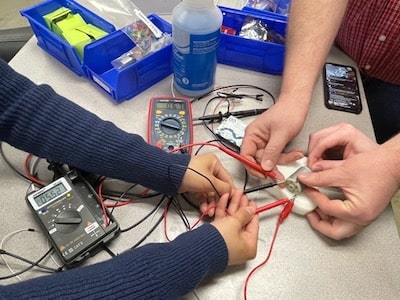
We also noticed that when we disconnected the motor from the battery pack and just turned the shaft by hand this generated a current.
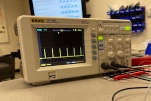
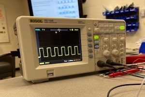
Something else we did in Lab was program an LED to fade in and out using pulse width modulation on an Arduino. Pulse width modulation works by changing the amount of time (in milliseconds)) that a digital signal is turned on or off. Even though the signal binary, you can get analog results by changing how often the signal switches on and off. We probed our LED circuit with an oscilloscope to study the actual width of the digital pulses, and as you can see the widths are changing over time.

Making the Board
Designing
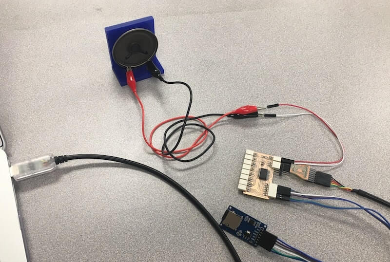
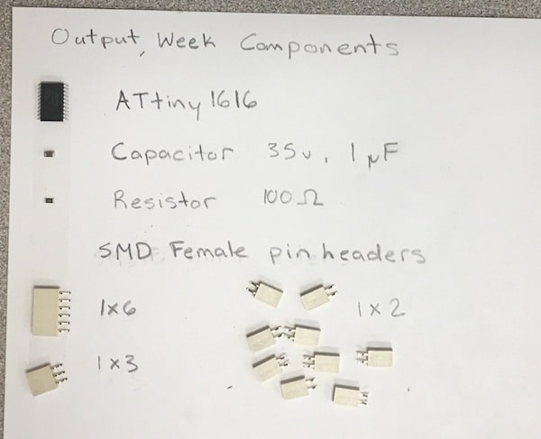
My hope with this week was to start making one of the electronic systems for my final project. I have an idea that I will want to have a speaker with multiple inputs, probably pressure sensors, but until I get those materials I'm using a set of buttons. Also, I wanted to give myself the option to try playing something from a .wav file stored on an SD card, so when I designed the circuit in KiCad I made sure to add pin connections for a Micro SD card adapter.
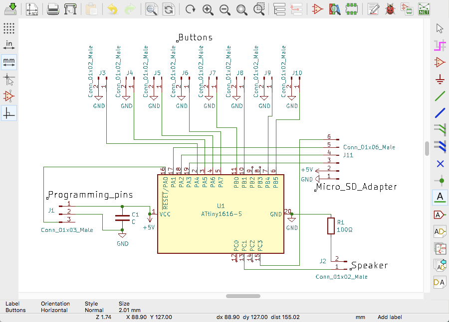
In KiCad, I used the symbol for an ATtiny1616-S for the microcontroller. Then, I added a capacitor, and a 1x2 pin header for the speaker with a 100 ohm resistor. Next to the speaker pins are a set of 1x3 programming pins, connected to data, GND, and VCC.
On the right side of the microcontroller is the 1x6 pin headers for the SD card adapter. These had specific pin connections which I had to reference the ATtiny1616 pinout diagram for. The SD adapter had labels that said that their pins went to VCC, GND, MOSI, MISO, SCK, and CS. I attached the 1x6 header accordingly. Although, when I designed the PCB I wasn't able to line everything up in the same order, which is ok, but I'll need to remember that when I go to plug things in.
All along the bottom of the KiCad circuit are 1x2 pin connections.
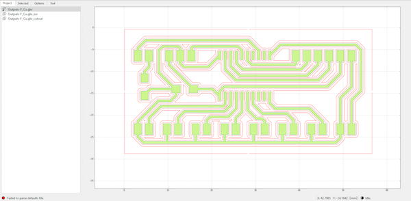
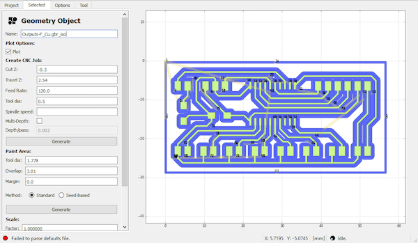
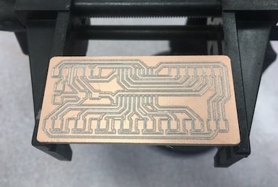
Milling
After plotting the Gerber file I opened the traces up in FlatCAM. Over the weeks, I've found that it's easiest to just make the cutout in this program too. So, I set up those toolpaths as I normally do, with a 120 feed rate, 0.5 mm tool diameter, -0.1 mm Z height for the traces, and -1.61 mm height for the cutout.
When I tried milling this, the traces hardly cut at all. Our Roland in the lab is known to be unlevel, but I secured my stock in the very center of the bed so that shouldn't have cause too much issue. I tried re-leveling the Z axis anyway on a different corner of the workspace, using my 1/32" ball nose end mill, but that didn't work either. So, I went back to FlatCAM and changed the depth of the traces. I tried everything from -0.1 to -0.3 mm but none of them seemed to make significant marks in the copper.
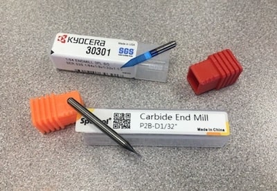
At some point I decided to check out the bit and make sure it wasn't broken or loosening up in the spindle. Neither of these things seemed to be the problem, but I switched out the collet for one of a similar same size, but guess what, that wasn't the issue either.
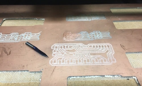
Then, I remembered we had "V" bits for the Roland. I used one of these for the traces, and the 1/32" end mill for the cutout. Since the tip of a "V" bit is much thinner than the normal 1/32" end mill that I usually use, I had to set the Z height to be lower than usual.
This finally worked! The traces were definitely deep enough, so there weren't any continuity problems to start, but the result did come out a little funky. Since I chose to do 2 passes, but didn't change the tool diameter, it showed up as two traces with a space between them. Not an issue. I could still solder it, but before I got to that I sanded and filed my board to clean it up.
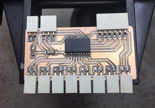
Soldering
Here, I gathered up my components to solder.
Soldering took a while, but it came out really well.
Programming
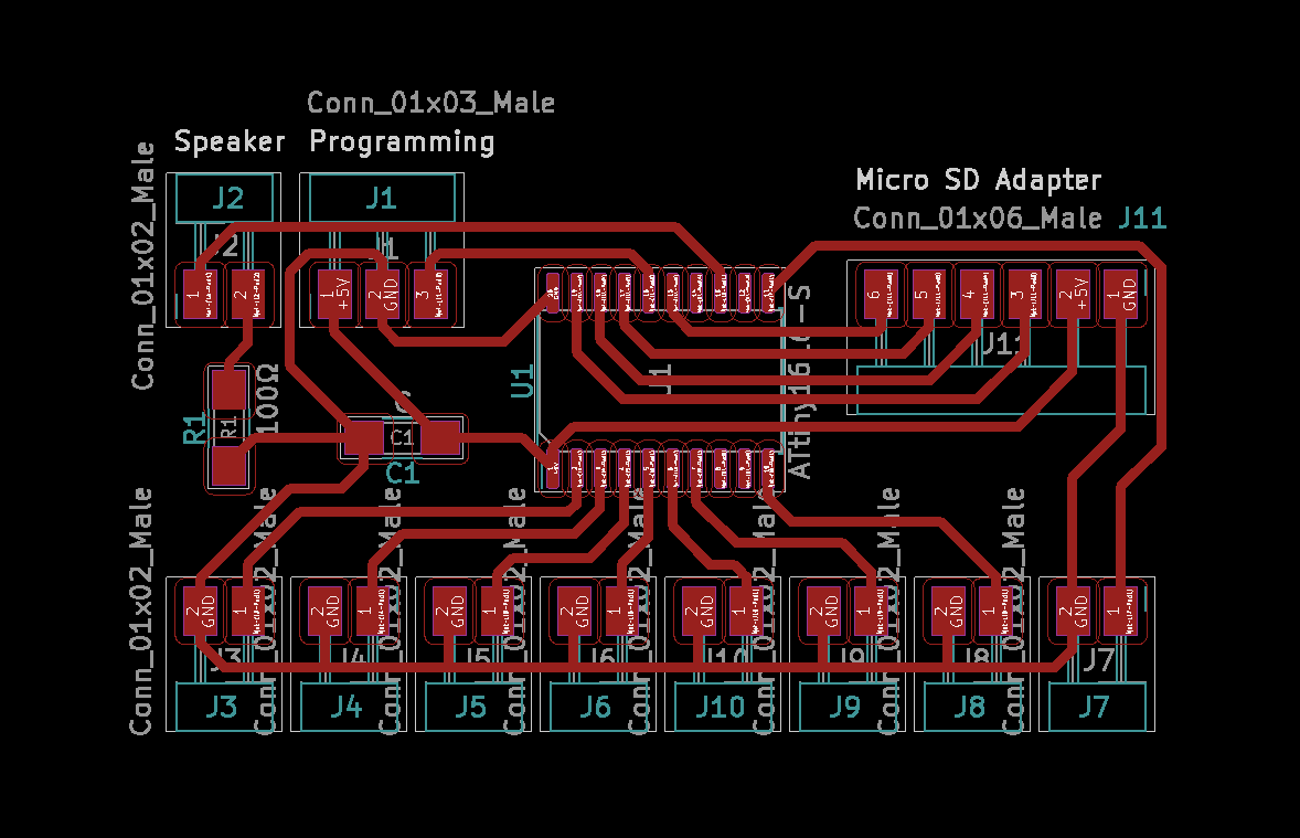
Unfortunately, the day after I soldered this I realized that I messed up on the circuit design. :( All of the 1x2 pin headers along the bottom are meant for button inputs, but I wired them as if they were LEDs. So, that leaves me with the speaker output on pin 13 and the connections for the microSD card adapter.
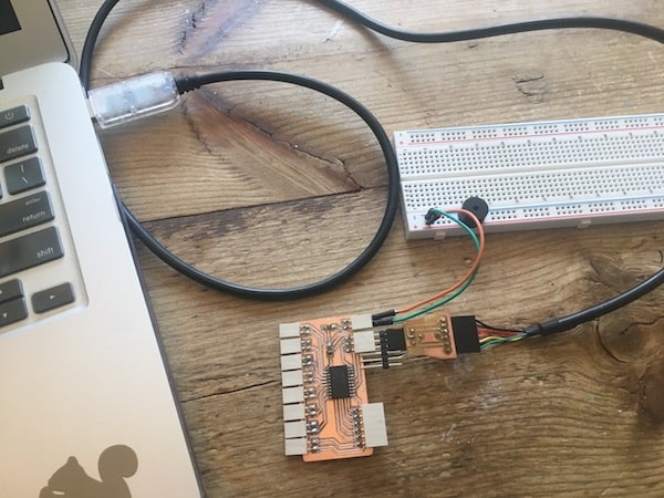
With these options, I decided to test a piezo buzzer with a simple toneMelody sketch from Arduino, but I ran into UPDI initialization errors when uploading the code. When I get back on campus I can do tests on my board to check the connections and the chip. From what I can tell, the cable is hooked up correctly to the programming pins and to the ATtiny.
SD Card Reader
Some days later...
I tried programming the same board again, and it worked, don't know what happened, might've been the cable. Anyway, once I knew that my speaker output functioned, I followed this Instructables tutorial which showed me how to play a WAV song file, stored on a micro SD card, on a speaker. I used an Arduino board to test this out.
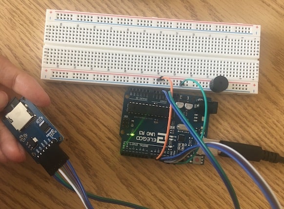
Essentially, I converted a downloaded song into a WAV format and saved that to the SD card. Then, there were specific pin connections for communication that the SD card reader made with the Arduino (CS, SCK, MOSI, MISO, VCC, and GND). In the Arduino IDE, I installed a new Library called TMRpcm which helps to play WAV files from and SD card. When I ran the code from the tutorial, the buzzer was super quiet, but I could hear the song. I noticed that in the TMRpcm library there was a function called setVolume. Through some trial and error, I learned that these speakers don't work the best when you set the volume to the max, they need to be at least a little bit under that for the sound quality to be clear.
I switched out the piezo buzzer for a slightly bigger one so you can hear the song in this video.
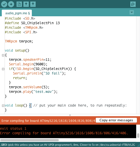
Now that I had both the speaker on my circuit board and the SD card reader on the Arduino working, I tried to combine them, but unfortuantly there was a issue with the compatibilty of my microcontroller's architecture and the TMRpcm library I was using in Arduino.
I think I probably could have found a way around this issue by using a different library, but since I knew that all of the components worked, I decided to try something else.
Arduino Melodies
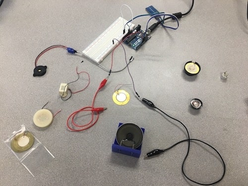
I knew I was going to want a louder speaker, so I had some fun trying out all of the ones I could find in the lab.
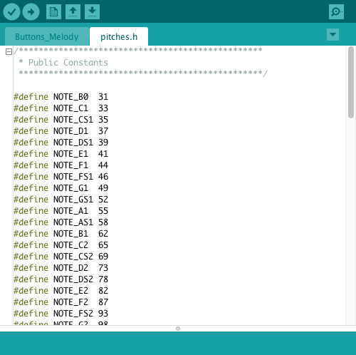
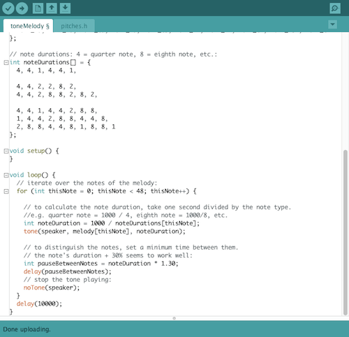
Using just the microcontroller and a speaker, not the SD card reader, I played a song by transcribing the notes into a program to run on my board. In Aduino's toneMelody example sketch, there is a file called "pitches.h", and it has a list of constants that assign a frequency value to every musical note. Middle C is labeled "NOTE_C4", with a frequency of 262.
Using my very limited knowlege of sheet music, I wrote down the notes and durations of the Doctor Who theme song. In short, this code works by listing all of the pitches and durations in their sequence, then iterating through to play each with the tone() function.
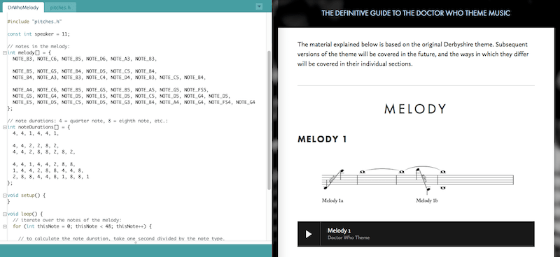
Play the video below to hear the programmed speaker!
Resources
- Pulse Width Modulation
- Audio Player Using Arduino With Micro SD Card
- Arduino tone examples: Tone Melody | Tone Keyboard
- Charlieplexing
- Multiple Push Buttons on One Arduino Input
- TMRpcm: Arduino Library | Troubleshooting
- Arduino songs: Translate Songs to Be Played on Arduino | "Take on Me" example
Design Files
Updated: May 15, 2021