MOLD MAKING AND CASTING
This week I designed and made a silicone mold which I then cast chocolate in.
This was the assignment:
- Review the safety data sheets for each of your molding and casting materials (in groups)
- Make and compare test casts with each of them (in groups)
- Design a 3D mold around the stock and tooling that you'll be using, mill it (rough cut + (at least) three-axis finish cut), and use it to cast parts.
Group Work
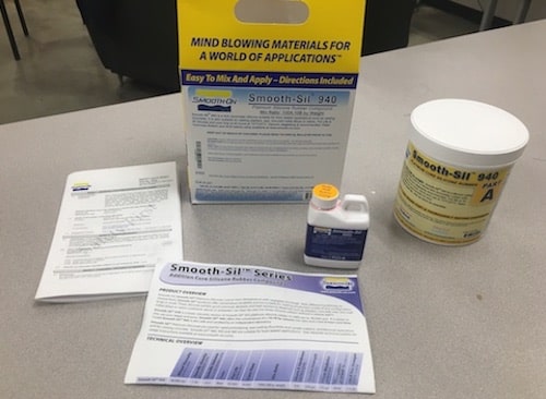
In our Lab, we made a couple of test casts using an expandable foam and a fast cast, white plastic. Most of our mold making and casting materials come from a company called Smooth-On. Their materials usually come in two bottles, Part A and Part B, which you mix together at a certain ratio.
By referencing the product overview sheet we can find the pot life and cure time. These tell you how long certain stages of the reaction will take. Pot life is how long you have to get the mixture into the mold once Part A and B are combined. It's basically how long you have until it becomes unmixable or unpourable. Curing time is how long it takes for the reaction to complete, or when it can be taken out of the mold.
The product sheet also tells you the ratios of Part A and B you should use, based on weight or by volume. For our first test, we used a material called FlexFoam-iT! III and the ratio for that was 57.5A : 100B by weight. Knowing that we wanted to use about 4g of Part B we calculated the amount for Part A, 3.2g.
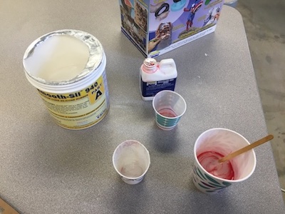
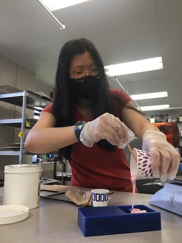
We measured these out on a scale and mixed them together. A good technique is to measure the parts separately, pour one into the other container, mix them well and scrape the sides, then pour the mixture into a fresh container and mix again. This helps ensure that Parts A and B are fully integrated. If you don't mix them well or if the ratio is off, then the reaction will not work properly.
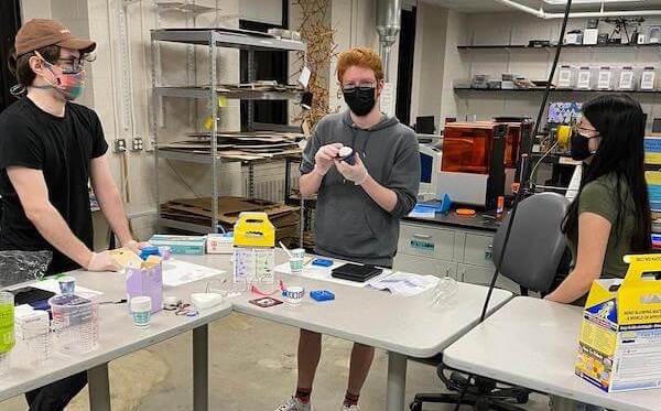
Here we are measuring and mixing our components.
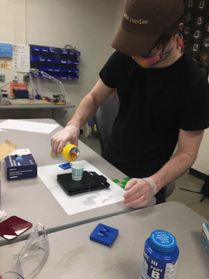
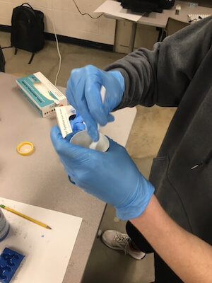
The pot life the FlexFoam-iT! III was 35 seconds so we had to mix fast. According to the technical overview sheet, this material could expand up to 15 times its original size! Because of this, after we poured the material into the mold, we covered it with a stiff sheet of acrylic with a hole in it, so we would get a flat edge for our cast object and the foam would have a place to escape through.
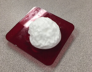
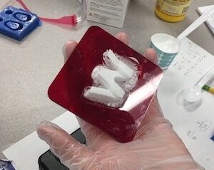
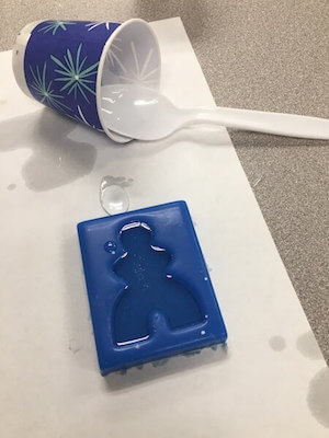
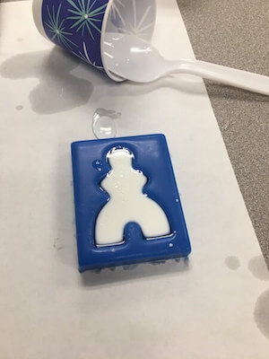
We also, tried the fast cast white plastic material which used a different mixture and ratio, but we went through the same steps in finding the ratio, measuring out Parts A and B, combining them, and pouring it into the mold. The fast cast white plastic was cool to watch because you could see the transformation.
In addition to testing these materials, my class found the specifications and safety data sheets for the different mold making and casting materials we have in the lab. My group researched VytaFlex molds and concrete as a casting material.
The safety data can be found on the back of the info sheets that come with the materials. It is really important to read these through to understand the hazards of the mixture that you're working with.
Each of the four groups in my class research the material properties and safety data of a different mold making and casting material. My group, "Come on Eileen" researched VytaFlex and concrete. Check out our spreadsheet HERE.
Mold Making
Fusion Design
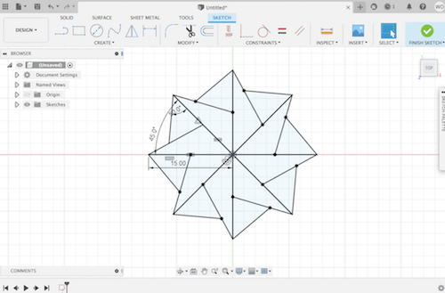
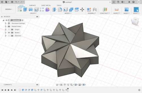
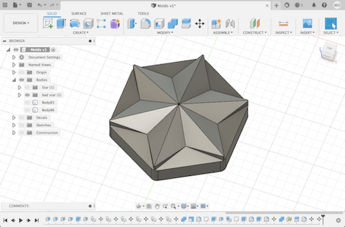
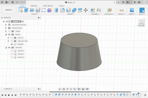
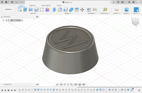
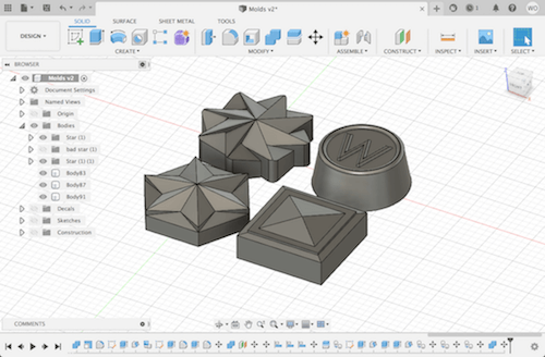
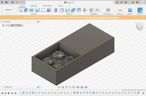
My first step was to design a mold. I used Fusion360 to create the shapes that I wanted cast, then I combined those designs with the carved-out shape of the wax block that I was using. This is the counter mold, and it's basically the mold for my mold. So, I'll carve this design from machinable wax and it'll serve as the tool that I use to shape the silicone mold.
Here is a brief glimpse at me making the designs in Fusion. I extruded the sketches and used the draft feature a bunch of times to make the slanted faces.
3D Manufacturing
My next job was to set up the toolpaths in the Fusion Manufacturing mode. This took a surprisingly long time from the issues I ran into.
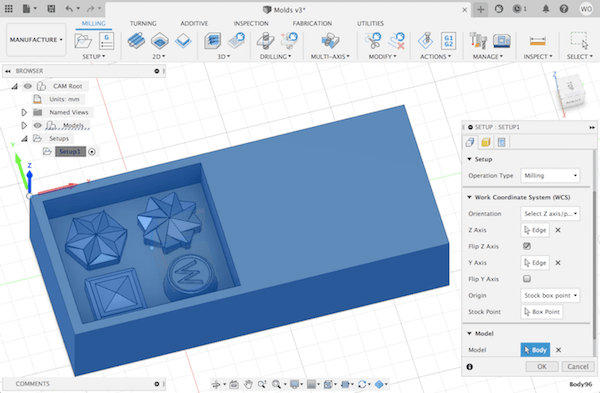
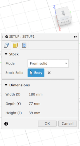
Like with 2D milling, I first created a Setup to tell Fusion my stock dimensions, where to put the origin point, and what directions to use for each axis.
Then, I created the roughing and smoothing toolpaths. A roughing pass is done with a larger bit and it's used to remove large chunks of stock. After that, you run a smoothing pass with a smaller bit to remove even more material so that the three-dimensional cut is more precise.
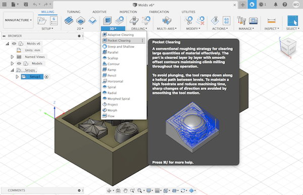
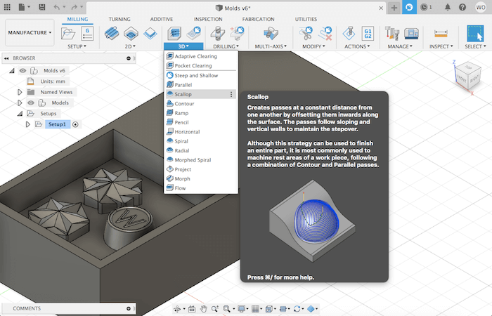
In Fusion, there are different types of toolpaths you can use, and depending on the geometry of your model one may be more efficient at clearing away material than another. I used a pocket clearing toolpath under "3D Milling" for the roughing pass.
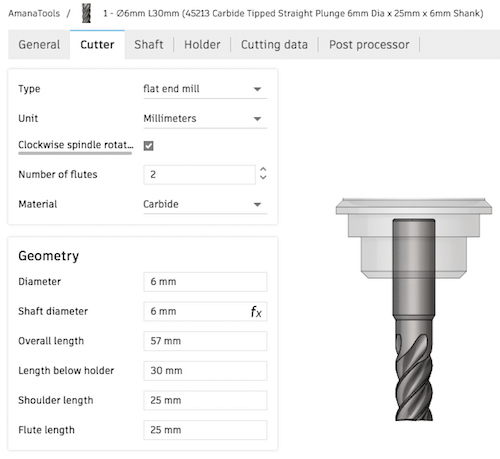
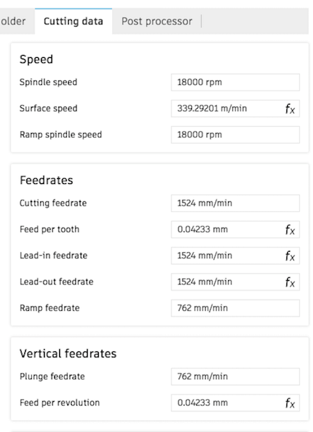
I chose the tool that I would use for the roughing pass, a 6mm flat endmill from the Amana tool library.
Under the Geometry tab, I selected the outline of the cavity for the machining boundary, that way it wouldn't try to mill anything outside of that green square. For "Model Surfaces", I selected the bodies of my 4 design units. The first time I tried to simulate this toolpath, I forgot to check the Model box, so it showed the bit going right through the 4 bodies.
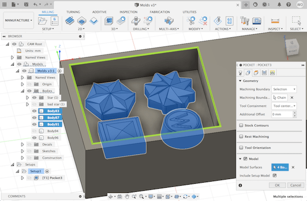
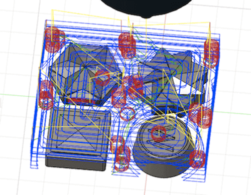
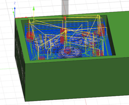
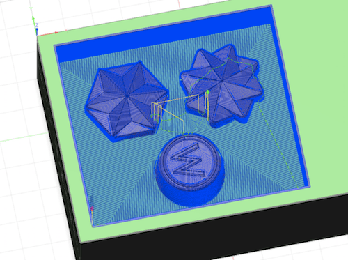
After that, when I tried to simulate the toolpath again, I got a warning message about some of the pockets being too small to be machined. Notice how the endmill doesn't pass along all of the sides in this simulation, this would make it difficult for the smoothing pass that comes after.
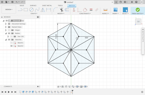
So, I went back to the Design workspace and edited the size and placement of the shapes to try to get them all to fit in the milling setup. It didn't quite work until I got rid of one of the shapes.
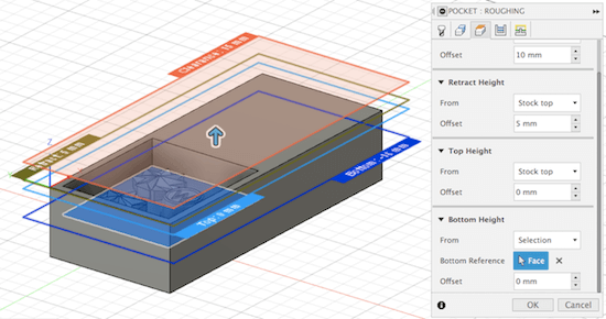
Going back to the Manufacturing mode, I re-selected the "Model Surfaces", and continued editing the Pocket tool path. Under the Heights tab, I made it so that the top height matched the top of the stock, and the bottom height was the base of the cavity.
Next, I changed the "Maximum Roughing Stepdown" to 2 mm. This is what people in my lab have found to work best with our mill. Be sure that it is the stepdown your changing, not the stepover. (I once tried editing the stepover to be 2 mm, and this made the toolpath be unnecessarily detailed for a roughing cut with a 6 mm diameter bit.)
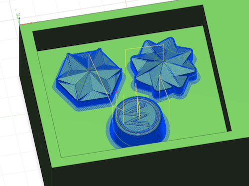
After that, the toolpath was ready to be simulated.
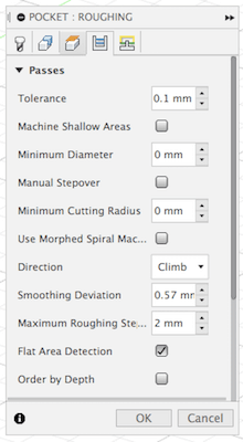
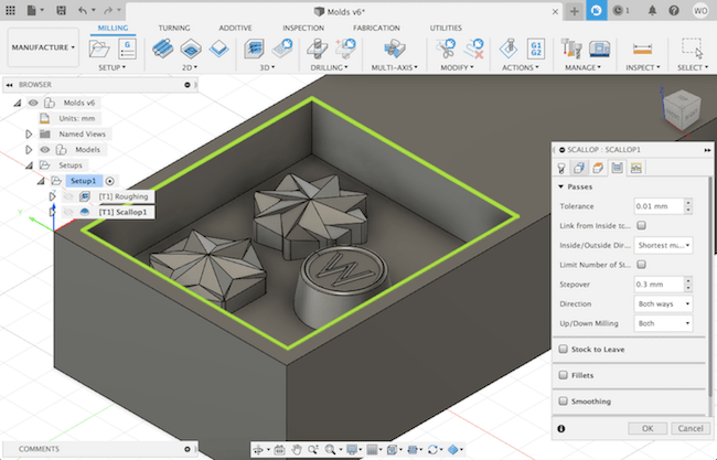
Once I had the roughing pass, I checked out a few different types of smoothing toolpaths to see what would make the most sense for the geometry of my shapes. I ended up going with a "Scallop" toolpath.
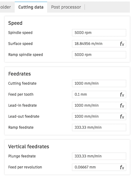
I used a much smaller bit, a 1.2mm flat endmill, for smoothing. These were its settings.
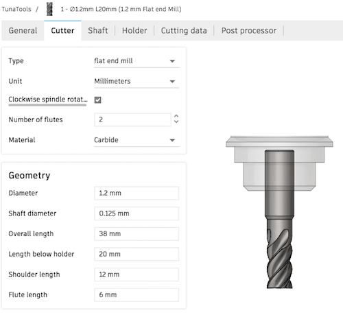
I had some trouble setting up this smoothing pass and getting it to load without taking forever. The first time I tried setting this up, I did it the same way as the roughing pass, except I changed the stepover to 0.3 mm (no manual stepdown).
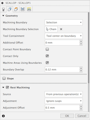
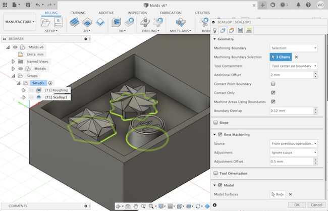
Then, I realized keeping everything else the same would make the mill run through the entire space of the cavity, even the sections that were cleared from the roughing cut. So, I needed to select "Rest Machining" under Geometry, which would take into account the parts of the stock that were already milled in the previous toolpath.
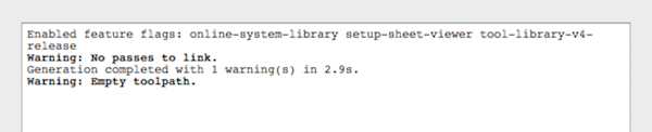
When I tried to simulate it, I got an error message saying I had an empty toolpath.
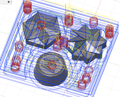
After being confused for a while, I went back to the roughing pass and double checked everything. I was able to fix something, but it still didn't work, so I moved my design to a different computer and made the toolpaths there. I also, tried combining all of the bodies, so when I went to make the toolpaths, I only had to select one "Model Surface". In addition, I changed the Scallop toolpath's "Machining Boundary" to be the outline of my 3 objects with a 2 mm offset, this made it so that the smoothing pass was confined to my 3 objects instead of covering the whole cavity.
Finally, I went to "Post Process" and saved each toolpath, one at a time, with Roland RML as the post processor and MDX-40 as the machine type. These saved as .prn files, which I stored on an SD card and brought over to the mill.
Milling the Mother Mold
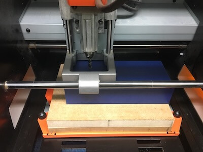
Compared to the manufacturing setup, the milling was surprisingly easy. I prepared the Roland mill by securing my machinable wax block to the bed with double sided tape, and I set the XY origin to the same corner where I had it in Fusion. This wax block with be the counter mold.
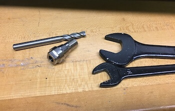
For the roughing pass first, I used the 6 mm flat end, upcut endmill. This had its own collet, which I took on and off using wrenches.
Then, I set the Z height to the top of the material and selected my file to start milling.
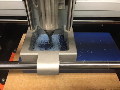
The Roland made a nasty sound when I started my roughing pass. I think it might have been the spindle speed that was too fast, but I didn't know how to change this once I started. Instead, I just dropped the feed rate to about 80% and that seemed to easy the Roland.
Because it generated so much wax, I paused the run a couple of times just to clear the space.
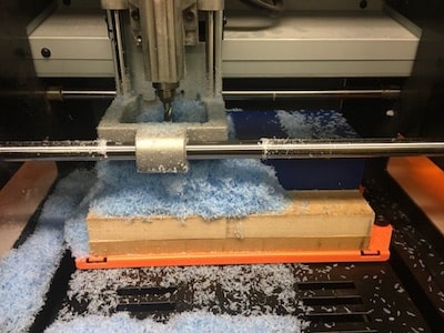
When I finished the roughing pass, I got a pop-up message on VCarve that said there was too much strain on the X axis. I had to turn the mill off and on to get it going again. Surprisingly, the XY origin stayed the same.
Next, it was time for the smoothing pass. I switched out the collet and endmill for the 1.2 mm bit. When I ran the file, I noticed that the indentation from the 1.2 mm bit was missaligned with the top of the circle created in the previous pass. This might have been from resetting the machine or it could have been a misalignment from using 2 very differently sized bits. Anyway, I fixed it by tweaking the XY origin until the start of the toolpath looked centered.
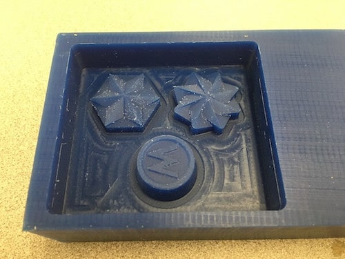
The smoothing pass milled really easily. Here's what it looked like when it was done. It turned out really well.
Smooth-On
The next step was making the silicone mold. Since I eventually wanted to cast chocolate, I used a food safe material, called Smooth-Sil 940.
From reading the product datasheet, I learned that this material had a 100A:10B by weight ratio, a 30 minute pot life, and 24 hour cure time. As a note, these materials are distinguished by their hardness. For instance, Smooth-Sil 940 has a Shore hardness of 40A.
I measured out 80g of Part A and 8g of Part B, and I mixed them together for a few minutes, making sure to scrape the sides.
Once they were fully integrated, I poured the mixture into the wax counter mold. To minimize bubbles, I poured a small stream in one place and let the mixture seep around and over my design.
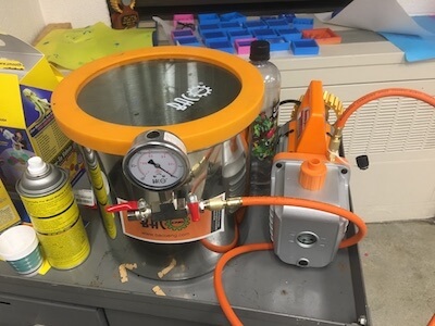
Then I tried using the vacuum degasser to pull the trapped air out of my mixture. Slowly the bubbles rose to the top, and I let the mold mixture cure for a day.
Be aware, if your counter mold or any of your mold making components are contaminated with certain chemicals, that might cause cure inhibition where the mold never fully cures, so make sure your design is clean and dry and that the material is suitable for whatever mold mixture you're using.
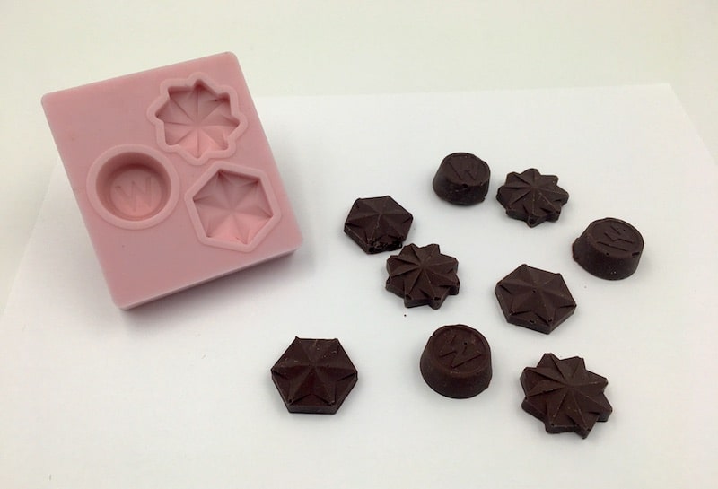
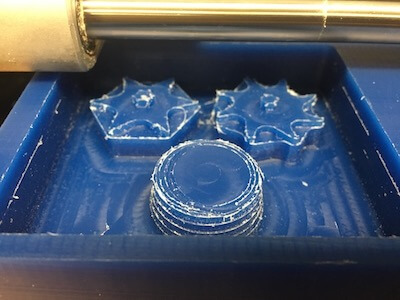
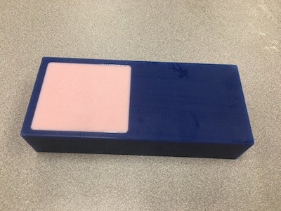
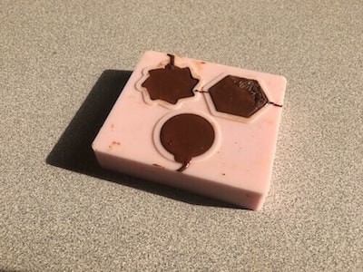
I didn't use release agent, but that turned out ok. After 24 hrs, I just had to pry up the silicone and there's my mold!

Casting
I decided to cast chocolate in my molds. So, I went through a process to temper the chocolate. First, I brought the chocolate up to 115°F using a double boiler. Then, I lowered it down to 80° by adding in more chips. I made sure not to get any water in the bowl, or else the chocolate would seize.
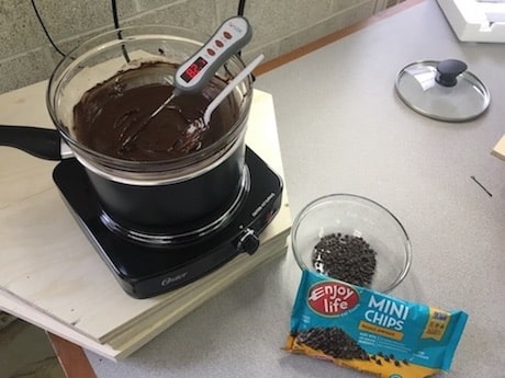
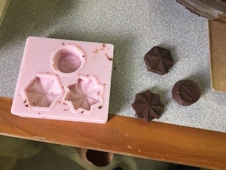
After that, I brought it up to a working temperature and did a swipe test to see if the chocolate would solidify within a few minutes. This worked, so I poured the chocolate into my mold and let it set.
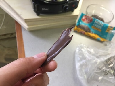
The chocolate came out really well! Now I can make cool personalized food molds with my initials.
Resources
- Smooth-On company
- Some materials: FlexFoam-iT! III | Smooth-Sil 940
- Mold making and casting terms and definitions
- Uxcell: 1.2 mm carbide flat endmill
- Amana Tool Database for Fusion
- SmallEndmill.tools for Fusion (includes 1.2mm and 1/32" bits)
Design Files
Wax_counter_mold.f3d (download link)
Design and manufacturing toolpaths
Updated: June 30, 2021