MECHANICAL DESIGN, MACHINE DESIGN
In these two weeks, my class designed and worked on the mechanisms for a SmartBar drink dispenser.
To visit the group page, click HERE.
Our assignment:
- Design a machine that includes mechanism + actuation + automation.
- Build the mechanical parts and operate it manually.
- Actuate and automate your machine.
- Document the group project.
- Document your individual contribution.
Initial Planning
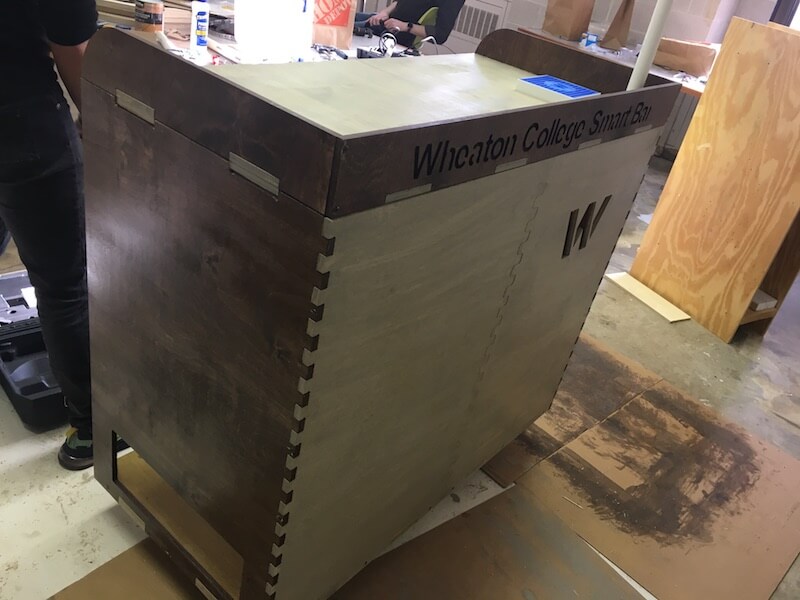
As a class, we decided to build a drink dispenser for our lab. Our vision for the "SmartBar" went through many stages. We started out thinking about doing some kind of water carbonation machine, but after several group meetings where we discussed our ideas, we settled on drink dispenser that uses pumps to move the liquid from a fridge to a spout and electromechanically operated valves to dispense a drink from a control panel. The touch screen panel is controlled by a Raspberry Pi, and the parts for the encasement were designed, then machined on a CNC.
Some Electronics
We fitted our SmartBar with NeoPixel lights and piezo speakers. These are controlled by a PCB with an ATtiny1616. Then we soldered the components and tested the speakers and NeoPixels with some Arduino code.
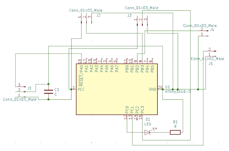
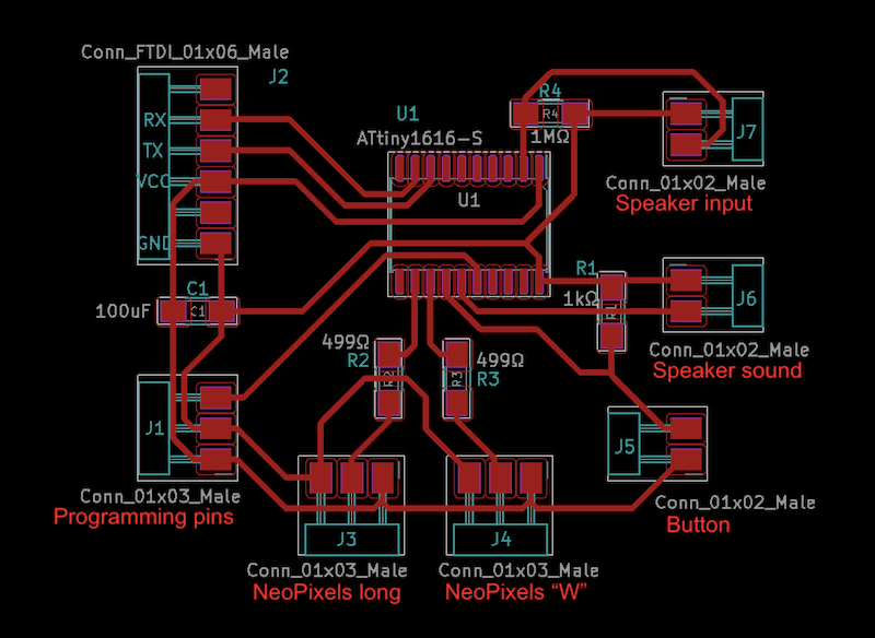
I designed a PCB with an ATtiny1616 that controls the NeoPixels and speakers on our machine. These were the schematics for my first attempt.
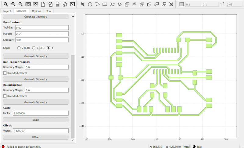
I also milled the circuit board on the Roland machine. Here I am setting up the NC files for the traces and outline in FlatCam.
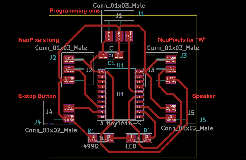
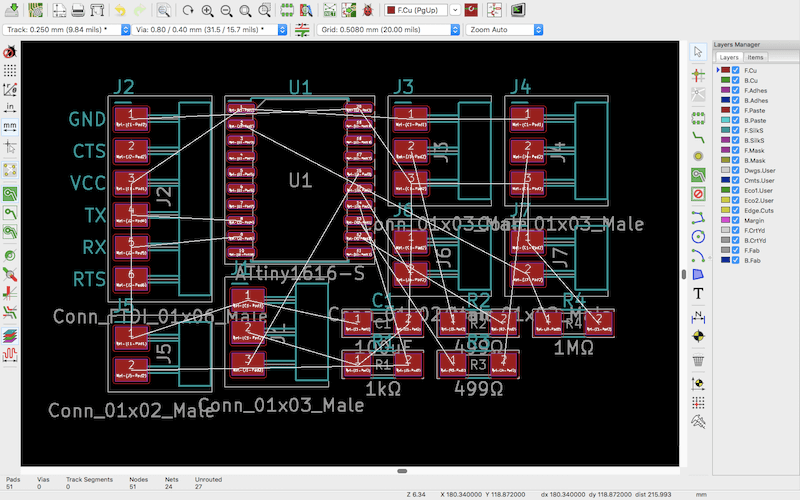
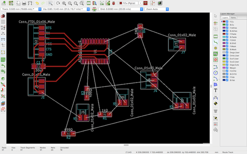
After milling this, I realized that I forgot to use a pull-down resistor for the button and that there were other pin connections that we wanted to include, so I modified the board design in KiCad and re-milled it.
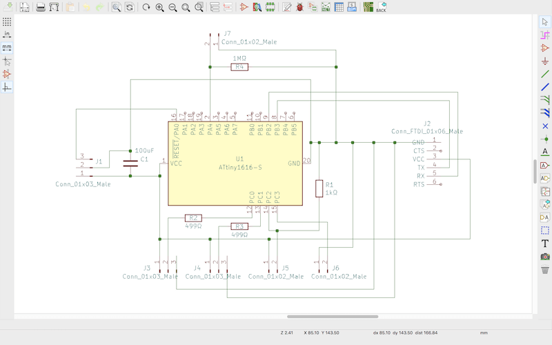
This diagram shows what each pin header will be connected to.
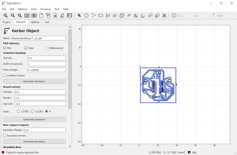
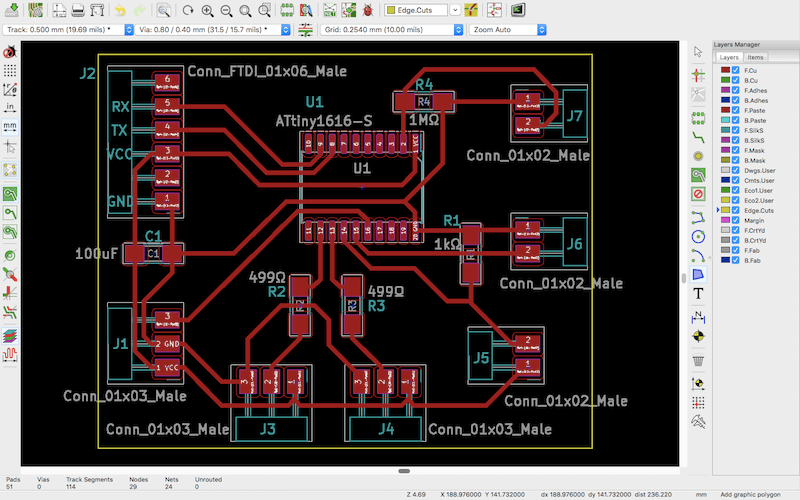
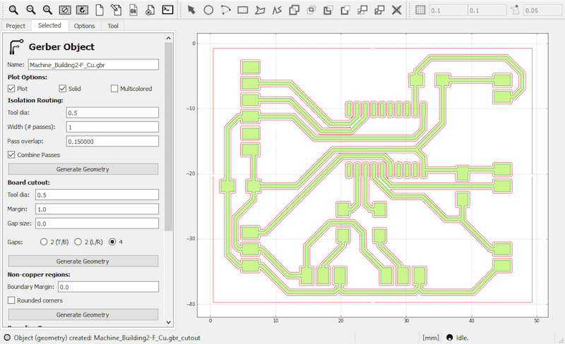
Next, I plotted the Gerber files and brought them into FlatCAM. Here I offset the design and set the tool diameter and settings for the traces and board cutout.
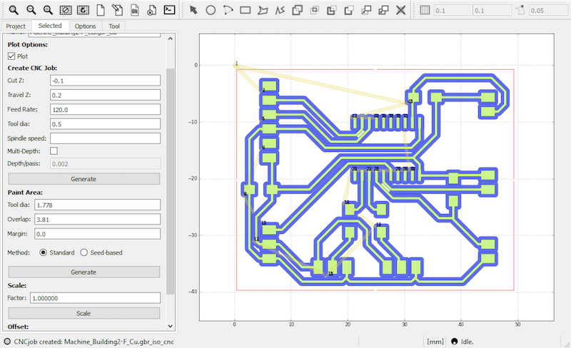
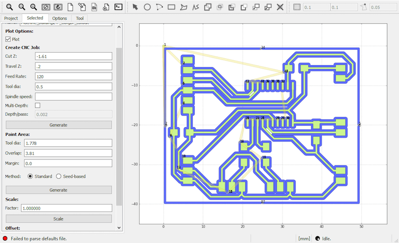
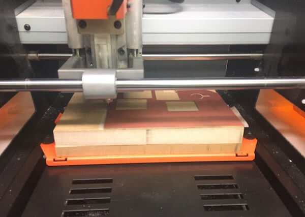
Once I generated the NC files for the outline and traces, I milled them on the Roland using a 1/32" carbide end mill and ball nose end mill.
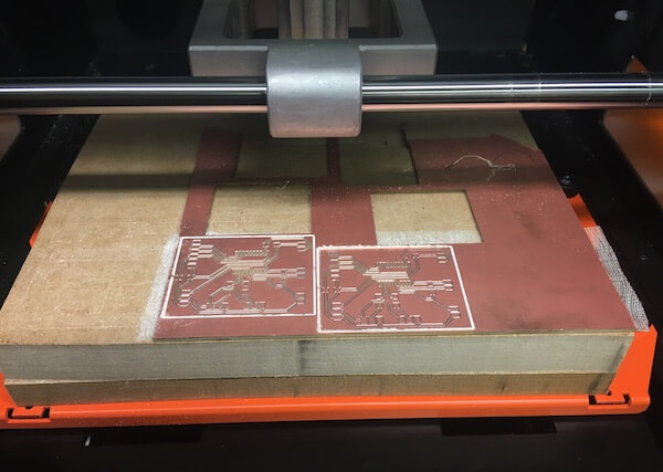
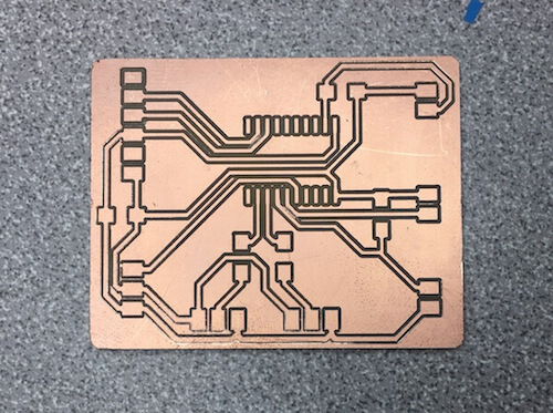
I milled it twice because the first one's traces seemed too thin. Here was the board after milling. Not all of the traces were fully milled, so I had to scrape some of the copper off of the bottom edge. I think this was because the bed was unlevel in the corner where was working.
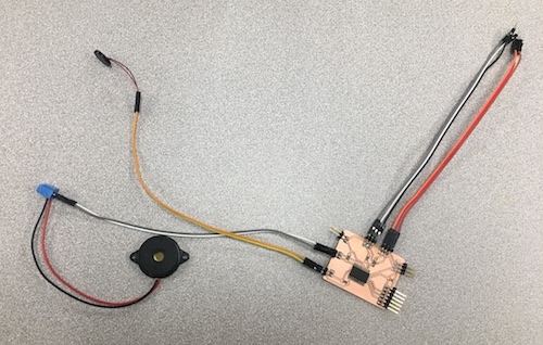
After Amanda soldered the components on, we tried a bunch of old speakers that didn't work. Then, I found this Arduino tutorial that shows how to use a piezo buzzer as vibration sensor to detect knocks. We programmed one buzzer as an analog input and another as a digital output. So, when the input buzzer detects vibration, the other one turns on and plays a tune.
For the NeoPixels, there are two sets of pin connections; one is intended to lead to a strip of blue NeoPixels to illuminate up the "W" in the case design, and the other is to light up the edges of the case.
I helped to troubleshoot the physical programming of our speakers and lights. For instance, when we were programming the lights, we got a "UPDI initialization error", which was an issue with bad solder and path connections, which we fixed with a combination of scraping the copper and resoldering elements.
After fixing that problem, we tried using an external power supply for the NeoPixels by attaching it to a USB cable and then plugging that into a wall outlet. We think this fried the pin on the ATtiny. We replaced this chip but got UPDI errors again. After trying a bunch of things, we replaced the ATtiny with a brand new one and everything worked out. Then we combined the NeoPixel code with the speaker song code.
With the Design team, I discussed how the electronic components would get physically integrated to the casing of the drink dispenser. I also provided feedback on the user interface regarding its functions and design.
Resources
- Fab Academy: Mechanical Design | Machine Design
- Arduino: Tone Melody | Knock | NeoPixels
- AdaFruit: Piezo element
Design Files
(includes schematic and PCB layouts for ATtiny1616)
Updated: April 7, 2021