COMPUTER CONTROLLED MACHINING
This week I used a CNC router to make something big.
Computer numerical control (CNC) is an automated manufacturing method by which machining tools are controlled by a computer-generated code. In the Wheaton Shop we have a 3-axis Axiom CNC router and a 5-axis ShopBot CNC mill. For this week, I used the Axiom to make 2D cuts on sheets of plywood.
This was the assignment:
- Test runout, alignment, speeds, feeds, and toolpaths for your machine (in groups).
- Make (design+mill+assemble) something big.
Group Work
To test the CNC, we made some shapes and toolpaths in a program, called VCarve Pro. This program is specifically made for making signs on a CNC router, so it's a bit limited in terms of design possibilities, but it can make simple shapes and text pretty easily. We decided to test three different types of toolpaths:
- profile = cuts along the edge of a shape
- pocket = cuts a shape's interior area at a specified height
- drill = drills a hole
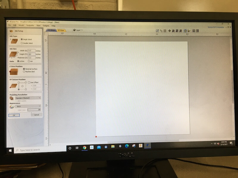
In VCarve, we entered our stock dimensions and set the Z height to start at the top of the material. Then we created some simple shapes.
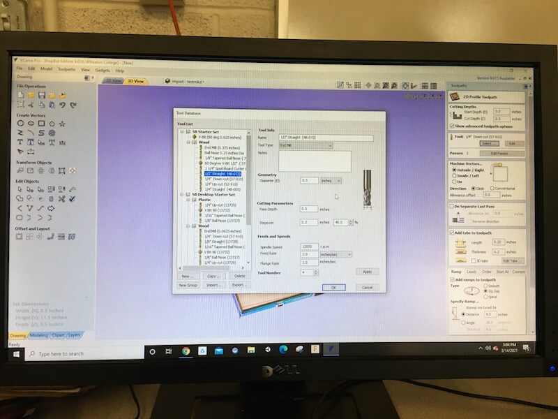
On the right side, we set up our toolpaths. For the profile and pocket cuts, we used a 1/4" down-cut flat end mill. In the tool settings, we decided to test the feed rate by increasing it from 2.6 in/sec to 3 in/sec. Pass Depth should be the same diameter of the bit and stepover should be no more than the radius of the bit. Spindle speed is controlled by the Axiom itself, and that's the rotational speed of the spindle. Plunge rate was set to 1 in/sec.
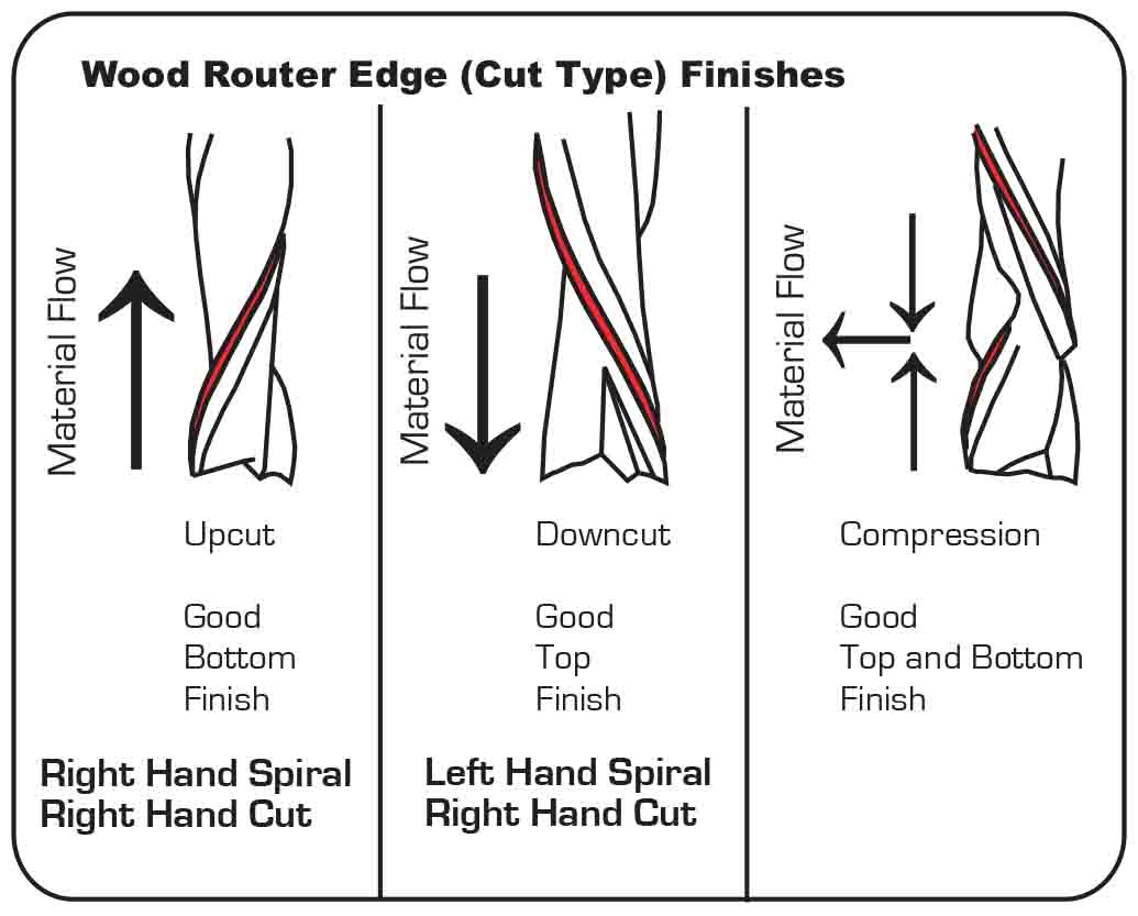
Since some of these toolpaths require different bits, I found it helpful to understand the difference between end mills and drill bits. End mills cut by moving sideways though the wood and drill bits cut vertically by plunging straight down.
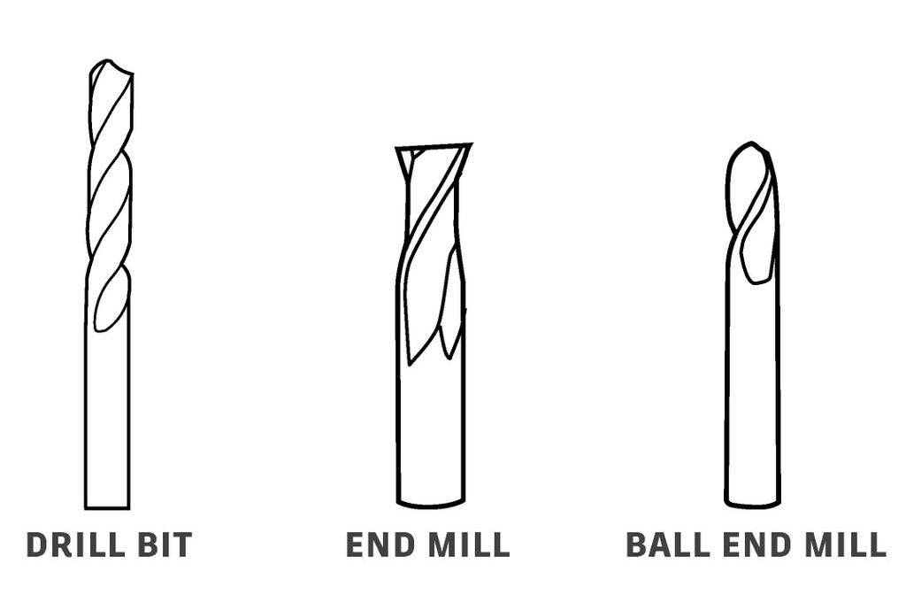
In addition, there are up-cut and down-cut bits. You can see the difference in the direction the flute spirals go. The up-cut will push the wood chips up and leave some damage on the top face of the wood, and the opposite is true for down-cut bits. There are also compression bits which leave clean faces on the top and bottom.
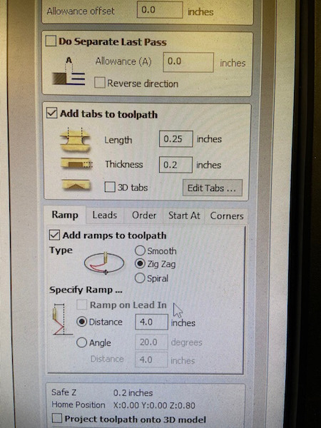
Back in VCarve, we set up tabs for the profile cut which will help keep the wood secure while cutting. We added ramps which will insert the end mill at an angle to reduce strain. Then we used a different bit for drill cut.
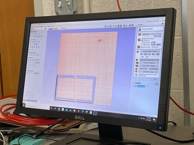
We simulated our toolpaths in VCarve and saved them individually to a flash drive.
On the Axiom, we set up our job by securing the stock to the bed and setting the X, Y, and Z origin points. When we started the job, we listened to see if we could hear any problems, but it seemed fine.
After removing our wood, we checked our CNC cut parts with a digital caliper to see how close to the intended dimensions they were cut at. This rectangle was designed at 2" x 4". In VCarve we had set the toolpaths to cut on the line so we could see the difference from kerf. Also, we tested alignment by seeing if two parallel cuts were actually the same distance from each other at two ends of the cut.
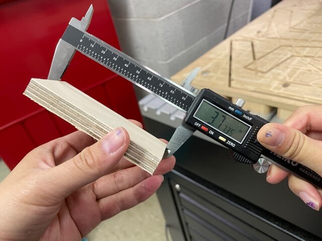
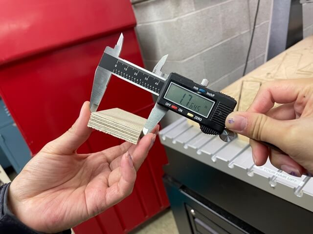
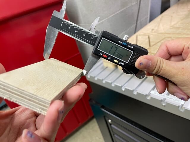
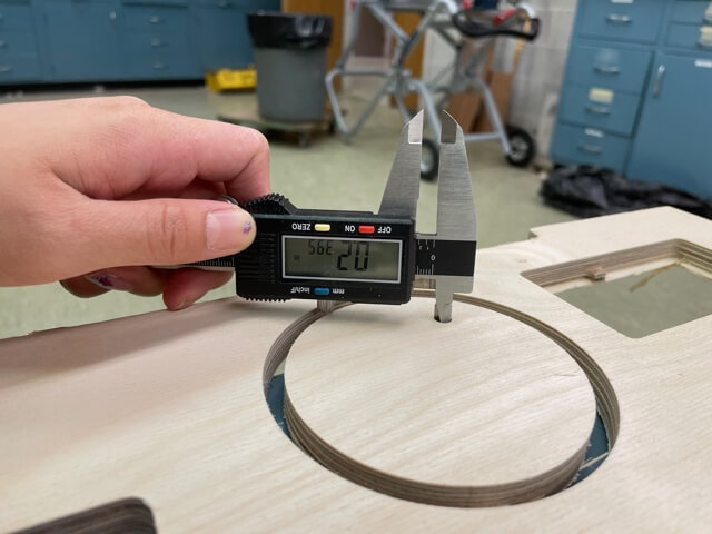
As expected, all of these actual dimensions were smaller. Lastly, we checked the runout by measuring a drilled hole to see if it was the same size as the bit and not larger. Our bit was 1/4", so didn't seem like runout was an issue with our machine.
Hexagon Seating Pod
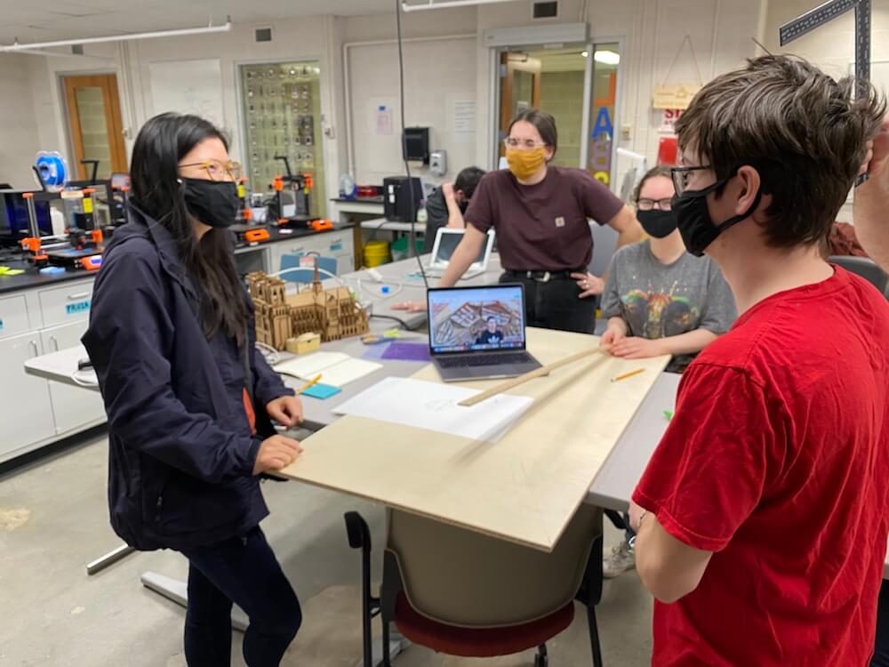
For my final project I'm working with Amanda to make a pavilion or indoor seating area. We decided to pair up with three other students to make the wooden structure for the Make Something Big week. You can read more about our brainstorming and design process on my Final Project page.
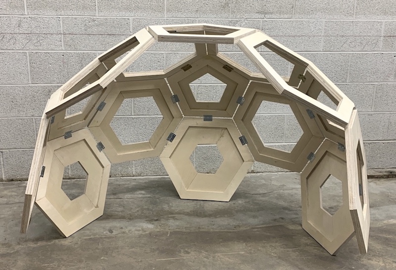
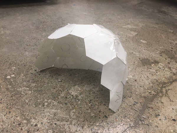
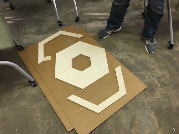
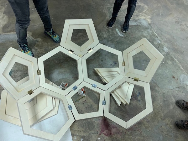
Our overall concept was a modular dome made up of hexagons and pentagon units. To figure out the placement of the hexagon units, we found it easiest to make a paper model first.
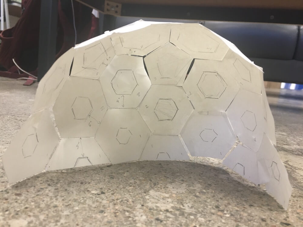
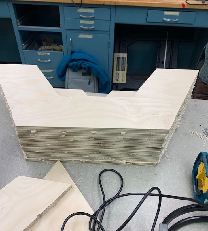
On Thursday, we met as a large group to figure out the logistics of how the dome structure and individual polygon units would be assembled, and also to estimate how much wood each shape would require. We figured the hexagons could be made by dividing them down the center and nesting them on the wood. Once they were cut out, we would attach the two halves and stack a couple hexagons on top of each other, at an rotational offset to make the seams stronger. Then, we had a few ideas about how to join the polygon units together, but eventually we settled on using small metal hinges.
Modeling in Fusion
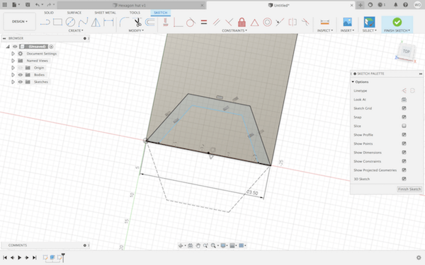
Once we had a design idea, we sketched out the two-dimensional parts in Fusion360. We each were allowed 4 sheets of 2' x 4' x 1/2" Baltic plywood, so with five people, we had 20 sheets of plywood to work with.
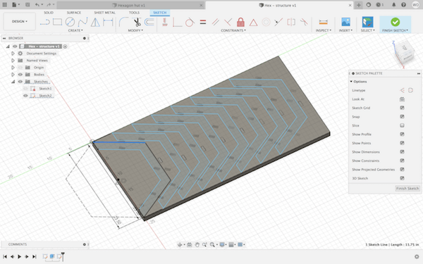
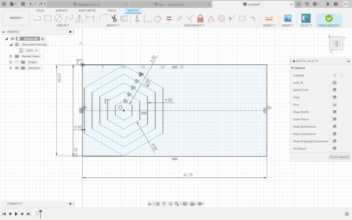
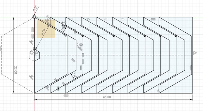
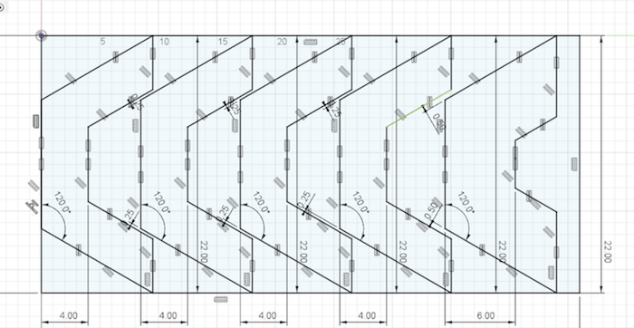
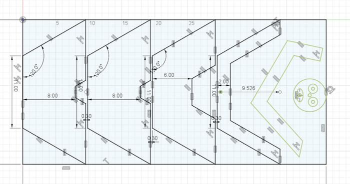
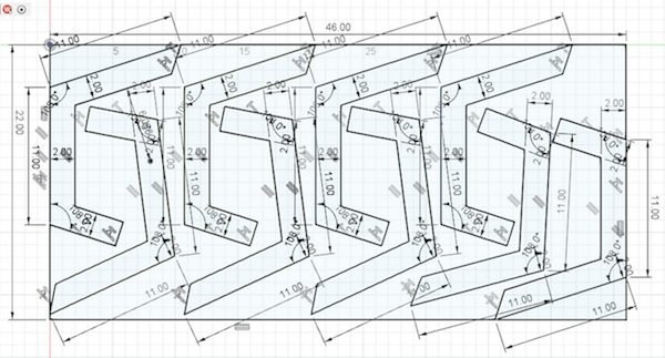
We had a lot of individual pieces spread over multiple cutting files, but for all of them, we basically went about designing them by making a polygon, adding an offset at a specified width (2", 4", 6" or 8"), cutting them in half, and nesting them in a 23.75" x 47.75" rectangle. Here are some snapshots of creating the designs in Fusion360. (See my Final Project page for more detail.)
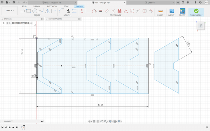
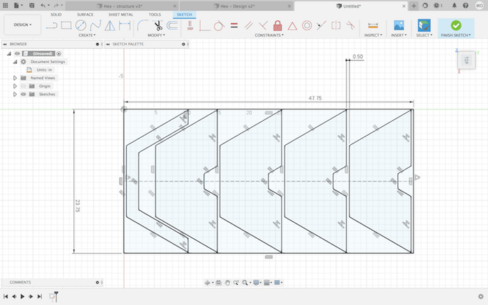
On Friday, we tried cutting our first file, but we found that our design was too large for the bed. Even though we designed within 23.75" x 47.75" and the bed is 2' x 4', because some of our shapes went right up to the edge, there wasn't enough room for the tool to exit the design space. So, we shrunk our shapes to fit in 22" x 46" rectangles. Along the same issue, we also found that the XY-origin on the machine had to be inset by an inch on either side. Once we finally cut that first file, we realized that some of our polygon angles were off, so we went back into Fusion to adjust and check all the constraints. Here are some examples.
Creating Toolpaths
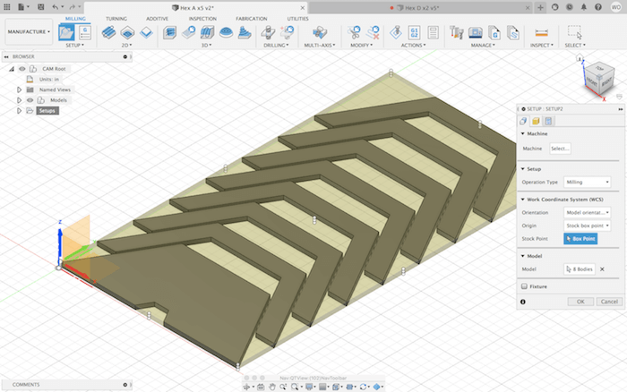
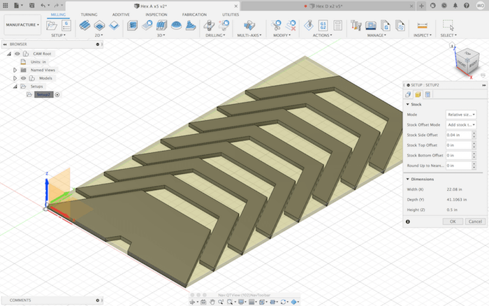
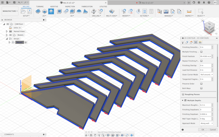
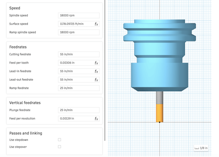
Once I had a good sketch, I extruded it and then, used Fusion's Manufacturing workspace to create toolpaths. First, I created a "New Setup", where I selected the origin point and the bodies I wanted to include. In the next tab, I set the stock dimensions. I chose this to be relative to the model size, with no top or bottom offset, since I had extruded my sketch to be exactly the thickness of the wood, .5".
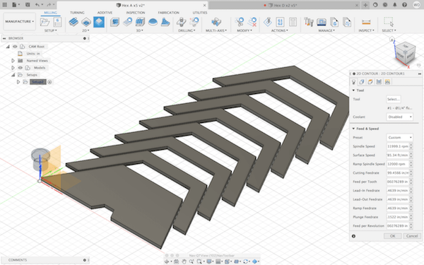
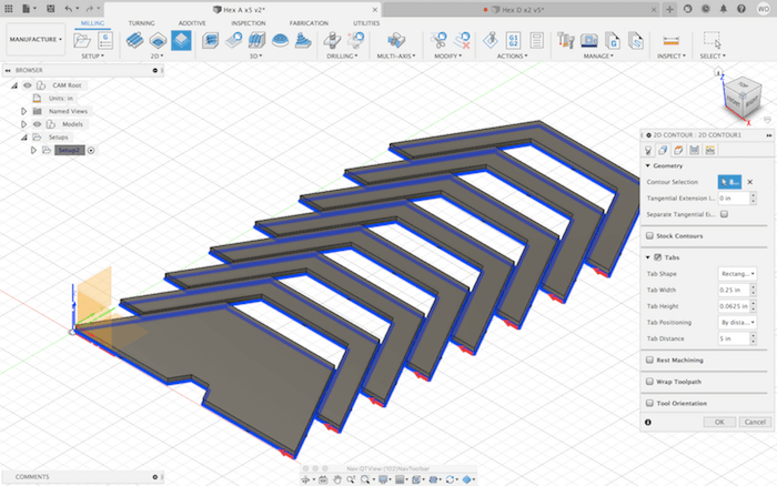
The only type of toolpath our designs required was a profile cut, so the next step was to create a "2D Contour". Here, I chose a 1/4" downcut flat endmill from the Fusion library as my tool. The given spindle speed and feed rate seemed reasonable, so I went onto the next tab. Under "Geometry", I selected the bottom edge of the bodies that I wanted to cut out. (The red arrow shows the direction of the cutting tool.) I added tabs as well, since these were profile cuts, but I found that the default was way too many, so I decreased them to be further apart. I selected "Multiple Depths" with a maximum stepdown of .2". This would help to reduce the strain on the endmill, which isn't designed to plunge straight down.
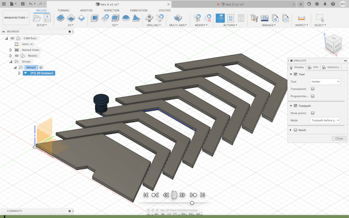
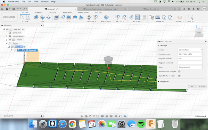
When I was done with the 2D Contour, I simulated the toolpath and didn't see any errors. So, I clicked "Post Process", chose "RS-274D / rs274" as my machine and generated the NC file, which I saved to a USB.
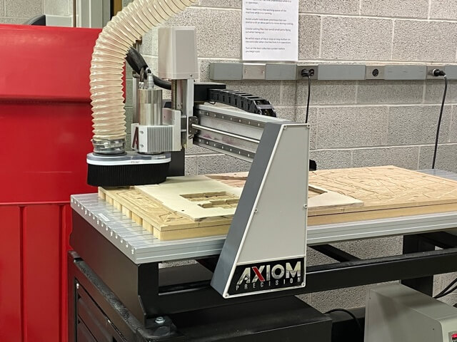
Axiom CNC Router
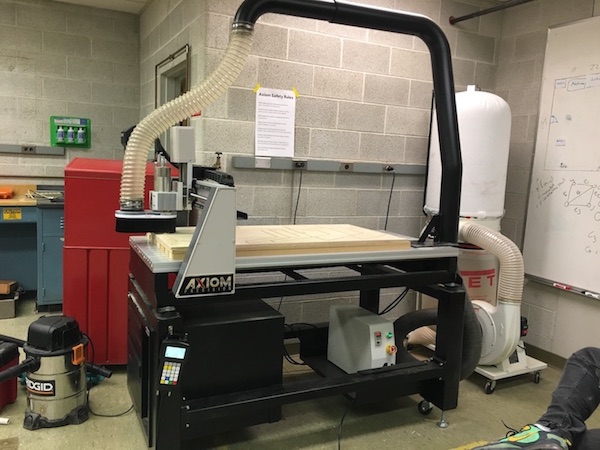
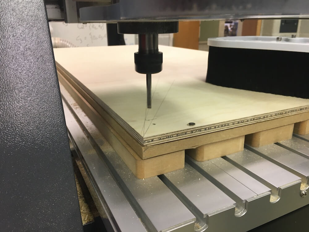
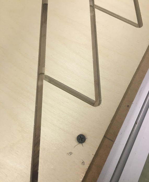
At the Axiom, we secured a sheet of 1/2" plywood to the bed with screws, making sure to place the screws in locations where they wouldn't get run over by the spindle.

We also set the XY-origin point to the lower left hand corner, and gave it about an inch of space from the edges. The correct bit was already in place, so we used a leveling tool to set the Z-origin to the top of the material.
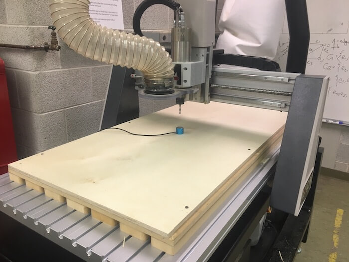
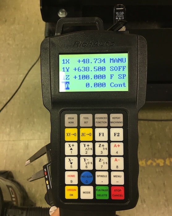
To start the job, I clicked "Run/Pause" on the control and navigated through the USB drive to find our job's filename. Then we turned on the dust collector and used safety protection before pressing [OK]. As it began, we listened as it began to make sure that it sounded like the machine was moving correctly.
There were so many problems that we ran into. Honestly, I feel like the sheer number of parts we had to cut gave us the opportunity to encounter almost every possible issue.
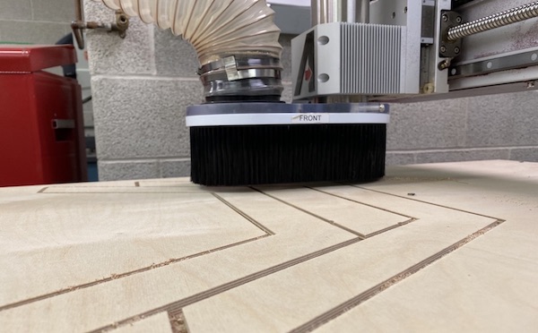
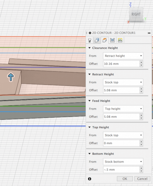
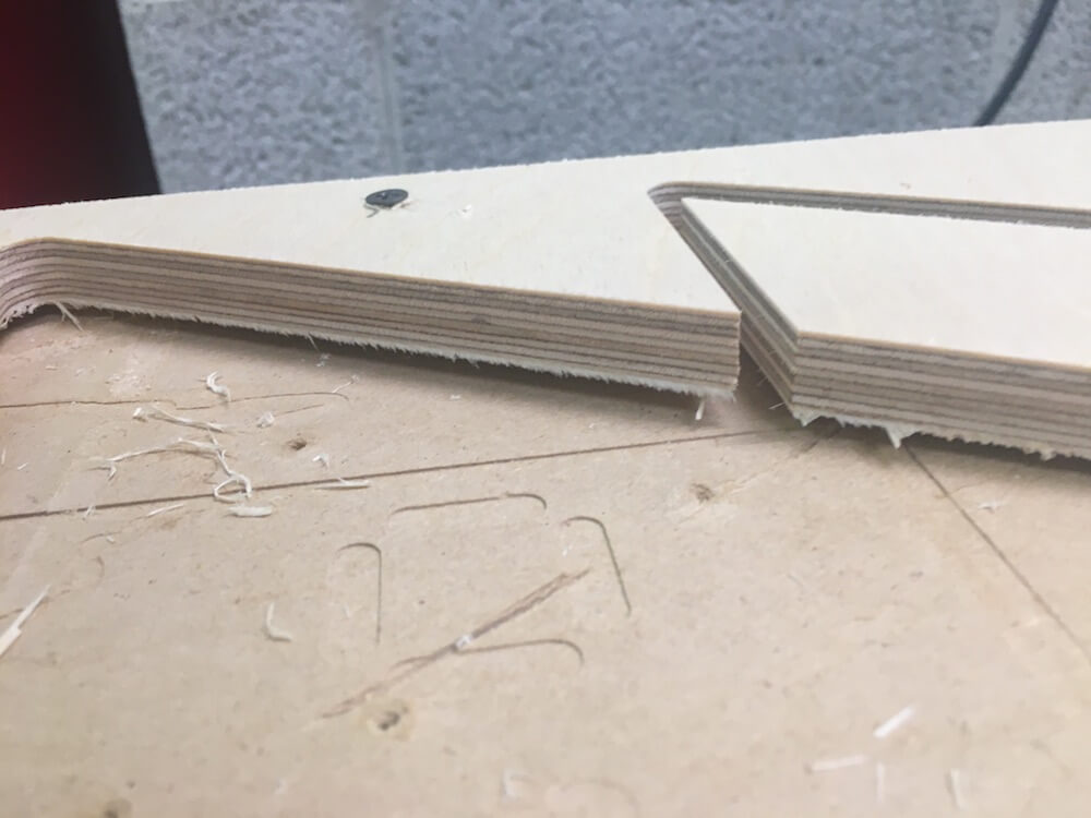
For instance, many of our earlier jobs didn't cut through the wood all of the way. We tried adjusting the bottom cutting height in Fusion to -0.5 mm or even -2 mm from the base of the stock.
This helped a little bit, but when we removed the parts we saw that the real issue was that the stock material way bowing upward, which was why it wasn't cutting through at the edges. When securing wood that's slightly warped, it's best to have the cupped edges sticking up, that way we can screw them down.
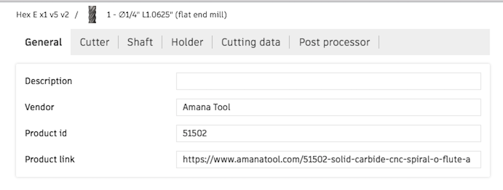
We also had a recurring issue where the spindle would move extremely slowly through the wood, like at about an inch every 10 seconds. We checked every setting in Fusion, especially the cutting feed rate, which was set at 99 in/min or 1.65 in/sec. This speed should have made the end mill move faster than what it was doing, but we increased the speed anyway and tried resaving the G-Code from various computers and Fusion accounts. We also thought it might be an issue with unit conversion, so we tested files in both mm and inches. None of these things worked. Eventually, we went back to the very first file that we were able to cut to see what tool was used. It turns out that the best working Fusion tool, with the correct machining settings, came directly from the Amana vendor, which is the tool brand of our Lab's end mill.
The settings from this tool worked on the Axiom at least for a while. However, the odd thing is that this tool has a feed rate of 55 in/min (or 1397 mm/min), which is about half the speed of the earlier attempt that went too slow. Even with these changes, the speed problem kept coming up intermittently. When this happened, we edited the G-code directly to increase the feed rate by a lot. Then, when we ran it on the Axiom, we could press [Y-] to lower the feed rate in 10% increments if necessary.
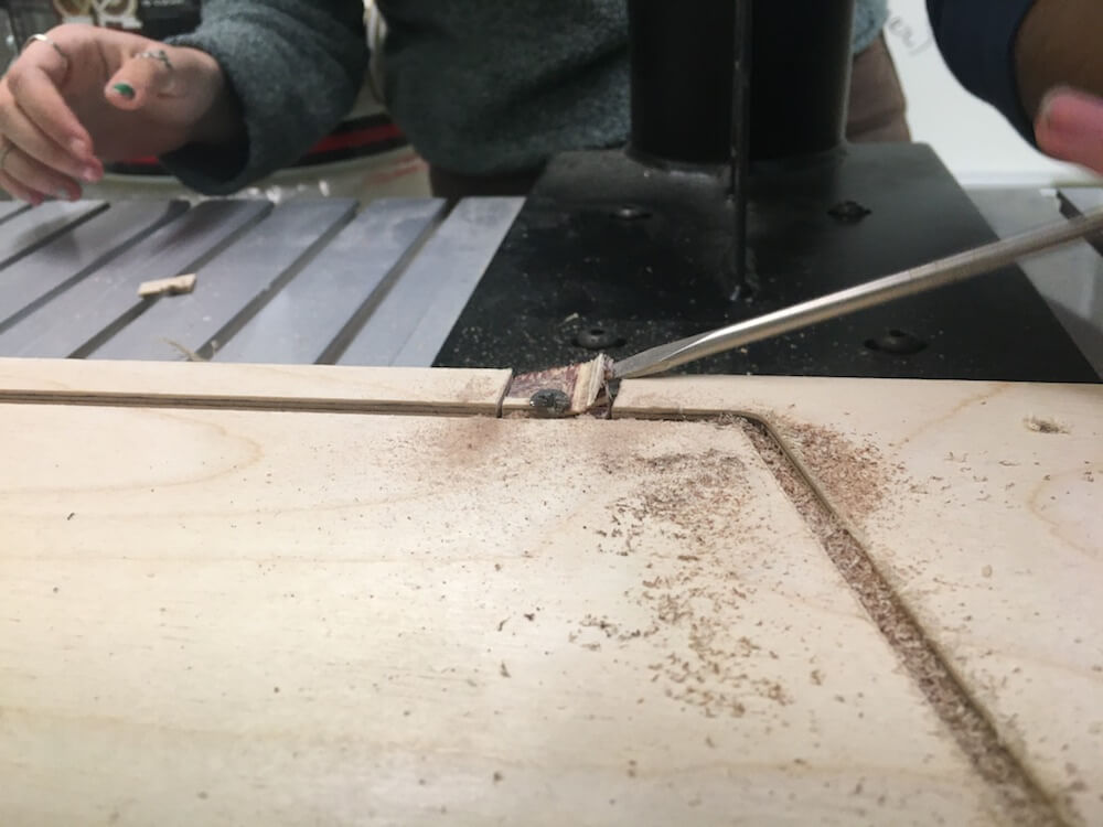
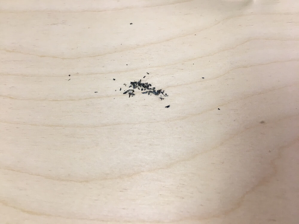
Another issue, we broke a bit by passing it through a screw. We had screwed the wood just a few millimeters too close to the workspace and you can see bits of the end mill were chipped off.
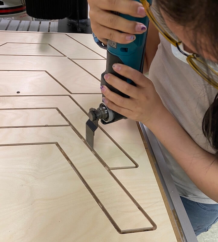
To remove the tabs we used an oscillating multi-tool.
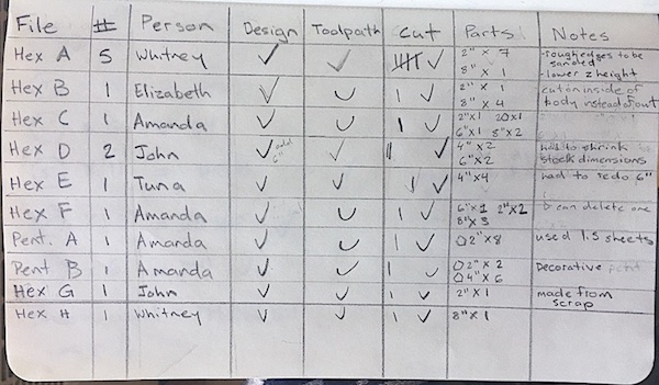
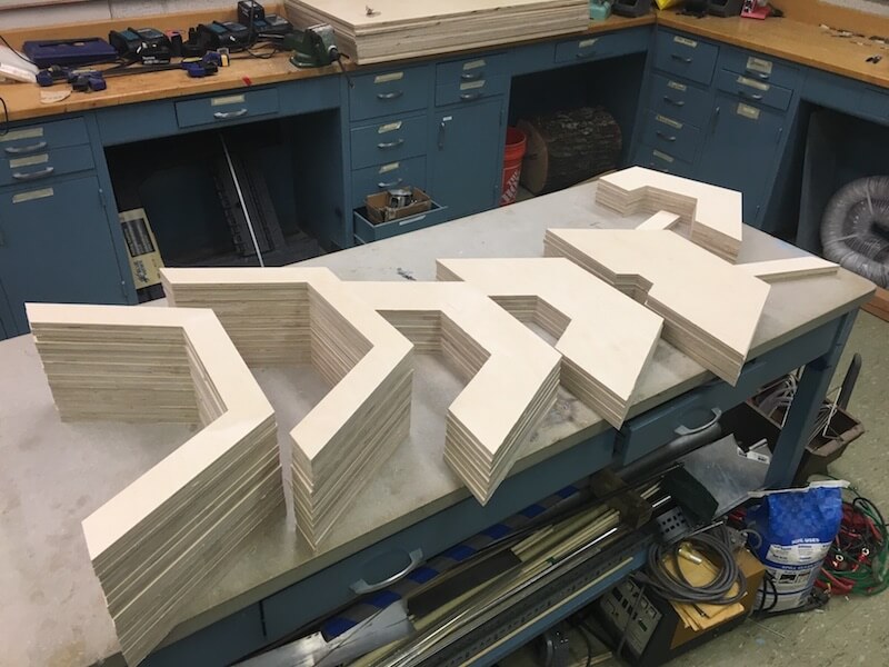
Over Friday and Saturday, our group continued cutting the polygon shapes on the CNC. These were some working checklists that I used to keep track of the different files and individual parts cut on the CNC. By the way, it isn't a good indication of any group member's involvement, all of us took part in an aspect of every cutting job. Also, as we worked, some of the shapes got messed up, either a cutting mistake or design flaw, so we added shapes to files and ran additional jobs on our scrap wood as needed.
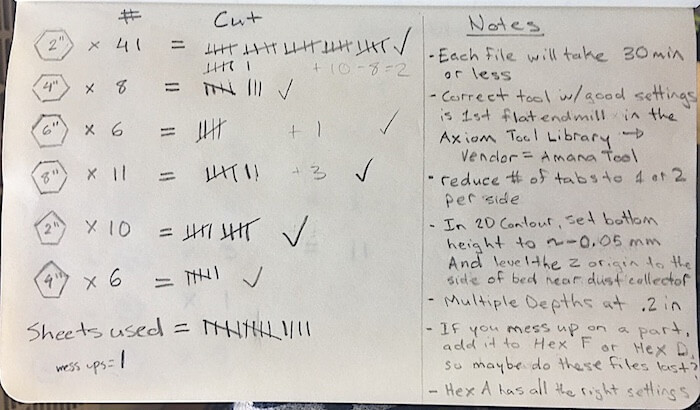
In the end, we used a total of 15 sheets of plywood. and 82 individual parts!
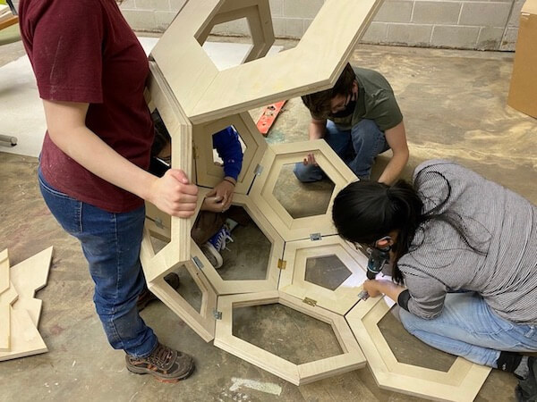
Assembling the Parts
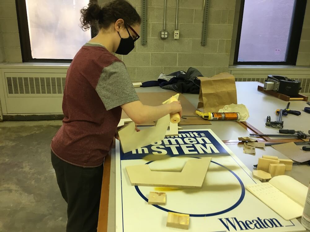
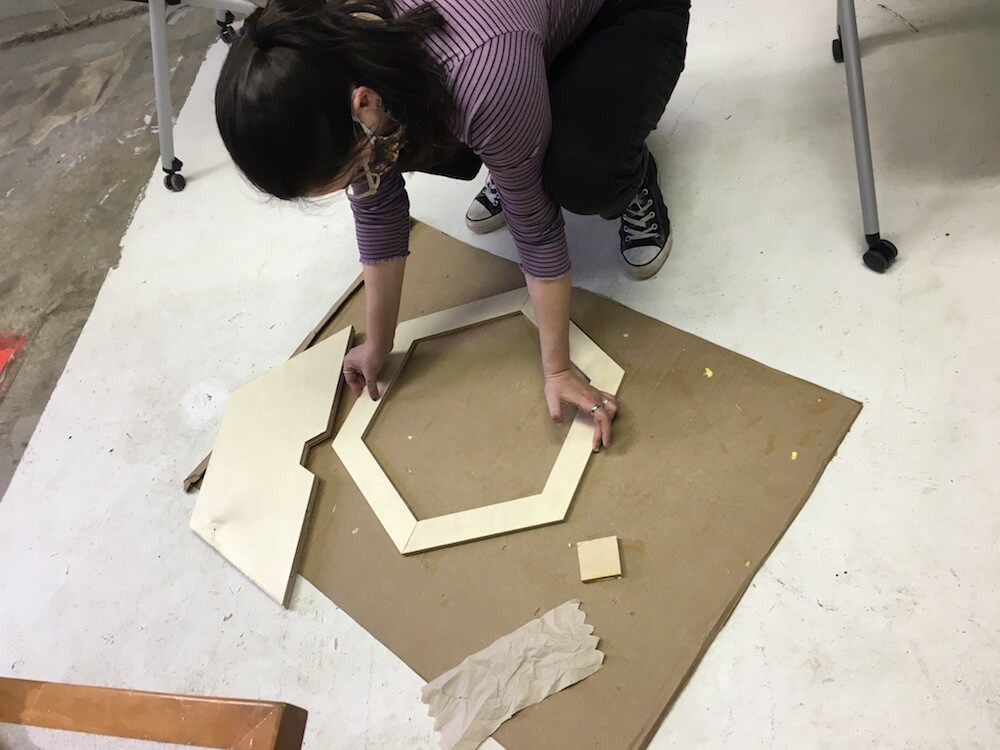
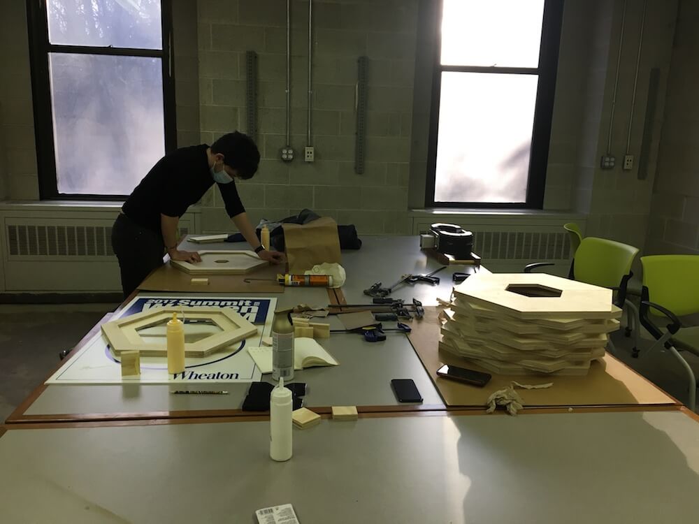
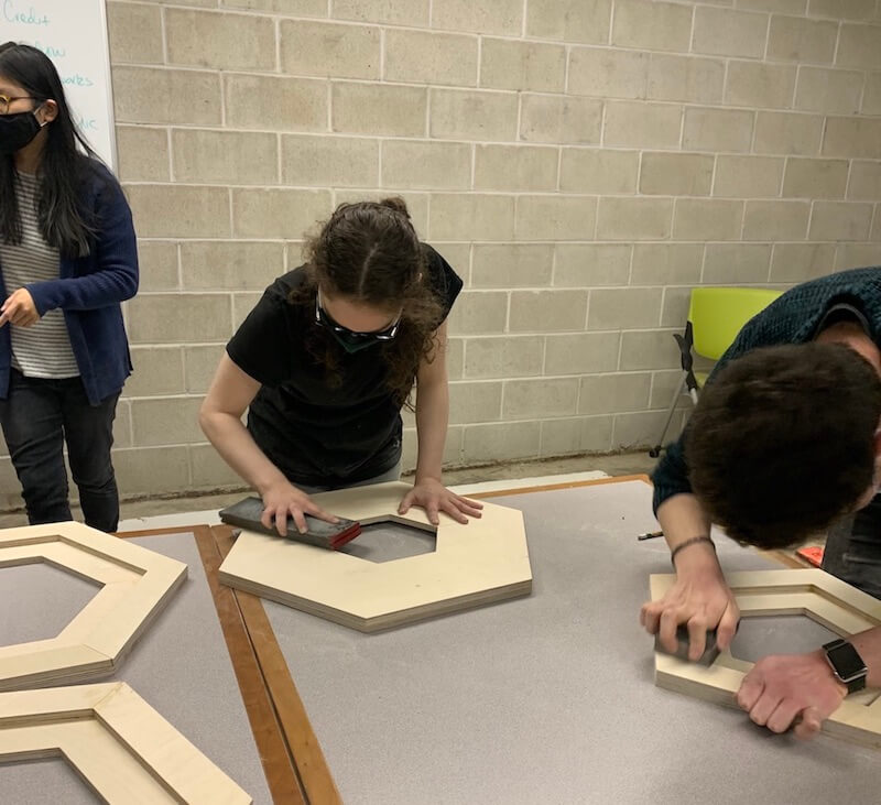
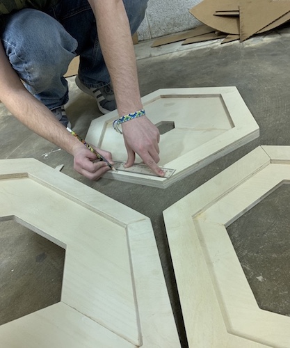
On Sunday, we worked on gluing individual parts to make up the polygon units. Our design was to piece together matching sizes and glue a 2" wide polygon on the back of each. We were careful about pressing the peices flush together, and letting the wood glue dry for 24 hrs.
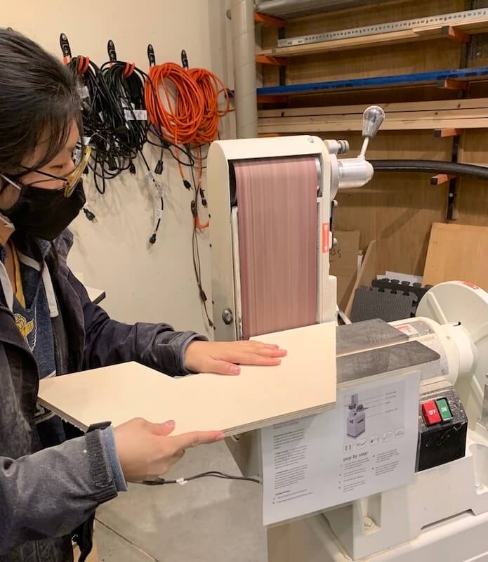
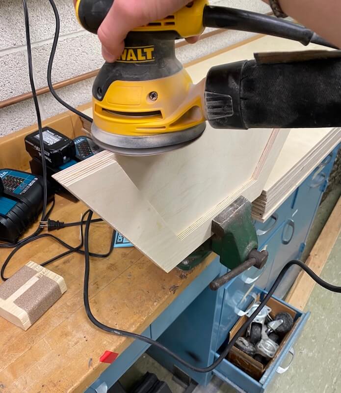
After that, we cleaned up the edges and residue glue with a combination of a belt sander, multi-tool, and hand sanding.
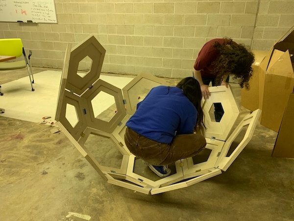
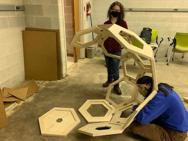
On Monday and Tuesday, we constructed the actual dome structure by attaching the hinges.
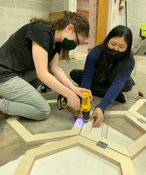
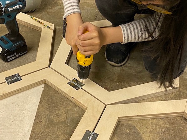
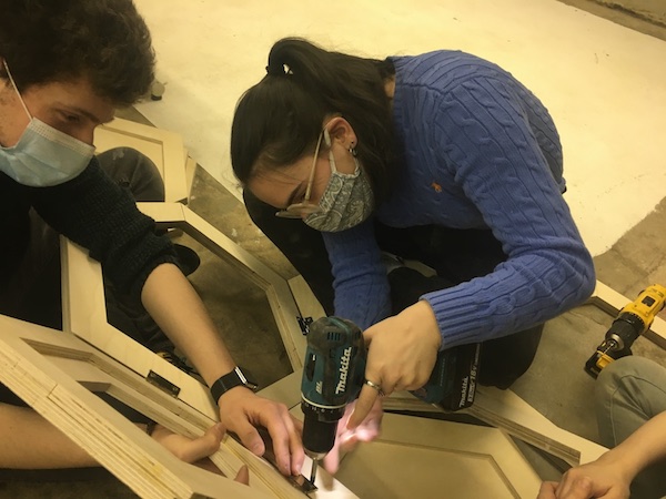
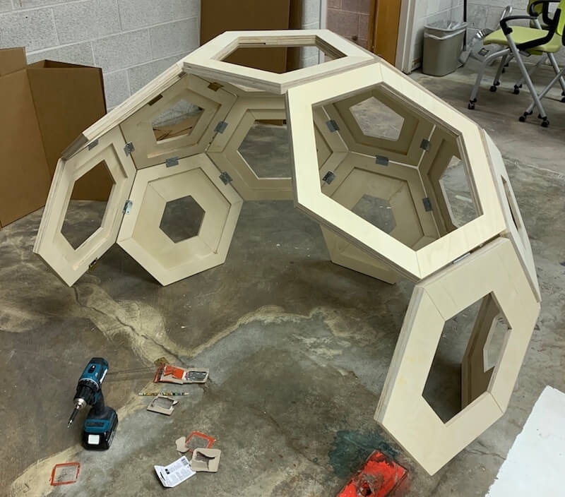
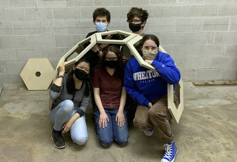
Here is our igloo/seating pod for Make Something Big week!
Resources
- Cutting tools: Drill bit/end mill, up-cut/down-cut
- Drill and milling styles: drilling, v-grooving, milling, spot drilling, chamfering
- End Mill Selection Guide
- Wheaton Fusion Tool Library
- Prof. Goodman Tutorials: Machining flat parts with Fusion 360 CNC Nesting parts and V-engraving
- Axiom Operation Manual
Design Files
Updated: March 17, 2021