Week 10
Input Devices
This week's assignment is aimed to make or modify our board that we have designed before, by adding a sensor and testing it.
Personal Project
For this week i wanted to start setting up my final project. So first i started with looking up different ways to find the range using sensors. There are multiple ways to do it but im choosing lidar. Lidar is an acronym of "light detection and ranging" or "laser imaging, detection, and ranging".
Lidar is commonly used to make high-resolution maps, with applications in surveying, geodesy, geomatics, archaeology, geography, geology, geomorphology, seismology, forestry, atmospheric physics, laser guidance, airborne laser swath mapping (ALSM), and laser altimetry. The technology is also used in control and navigation for some autonomous cars.
After some research I got around to getting this lidar sensor for its price and compatibilty with I2C.
After that I started designing the board. It took me a while to figure oout how to make the board.I ended up with this:
As you can see it still shows that there is one connection incomplete. That is because there is no other way to design the board without making a false resistor path over there. After this i had to mill the board. After 3 tries i finally milled the board and got the soddering done.
I then used the arduino software to code the chip. I used the ATTiny 1616 chip. It took me a while to find a useable library for it but i eventually ended up using this
Group Project
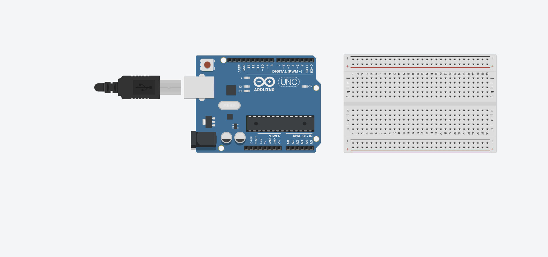
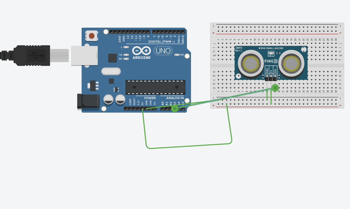
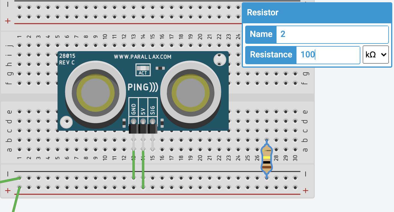
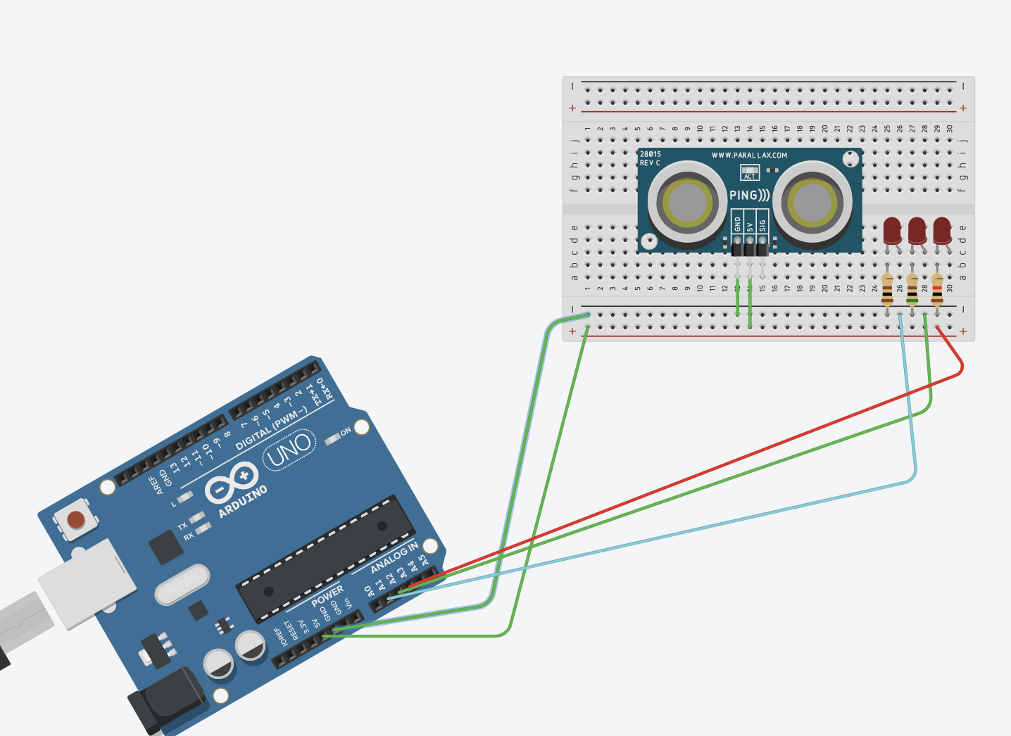
For our group assignment this week, we tested a few input devices and how they worked. we used variety of different devices, a breadboard, a 5V power supply, a resistor and various input devices. We then used the breadboard to layout our circuit and we used the resistor to record the voltage changes using a multimeter across the resistor after we connected the input devices and played with them.
Here you can see us putting the test breadboard together