Jacob Libby
Week 4
Electronics Production
A week dedicated to learning about milling with the Roland and exploring the world of circuitry and soldering
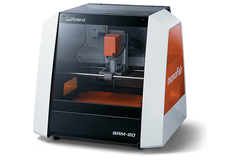
This is our Fab Lab's beautiful Roland SRM-20. And I know what you're thinking, it's on sale for only $3,995? Yes it is. This week we dove deep into this tool and its partner-in-crime of a software VPanel (please excuse the exceptionally lamer link).
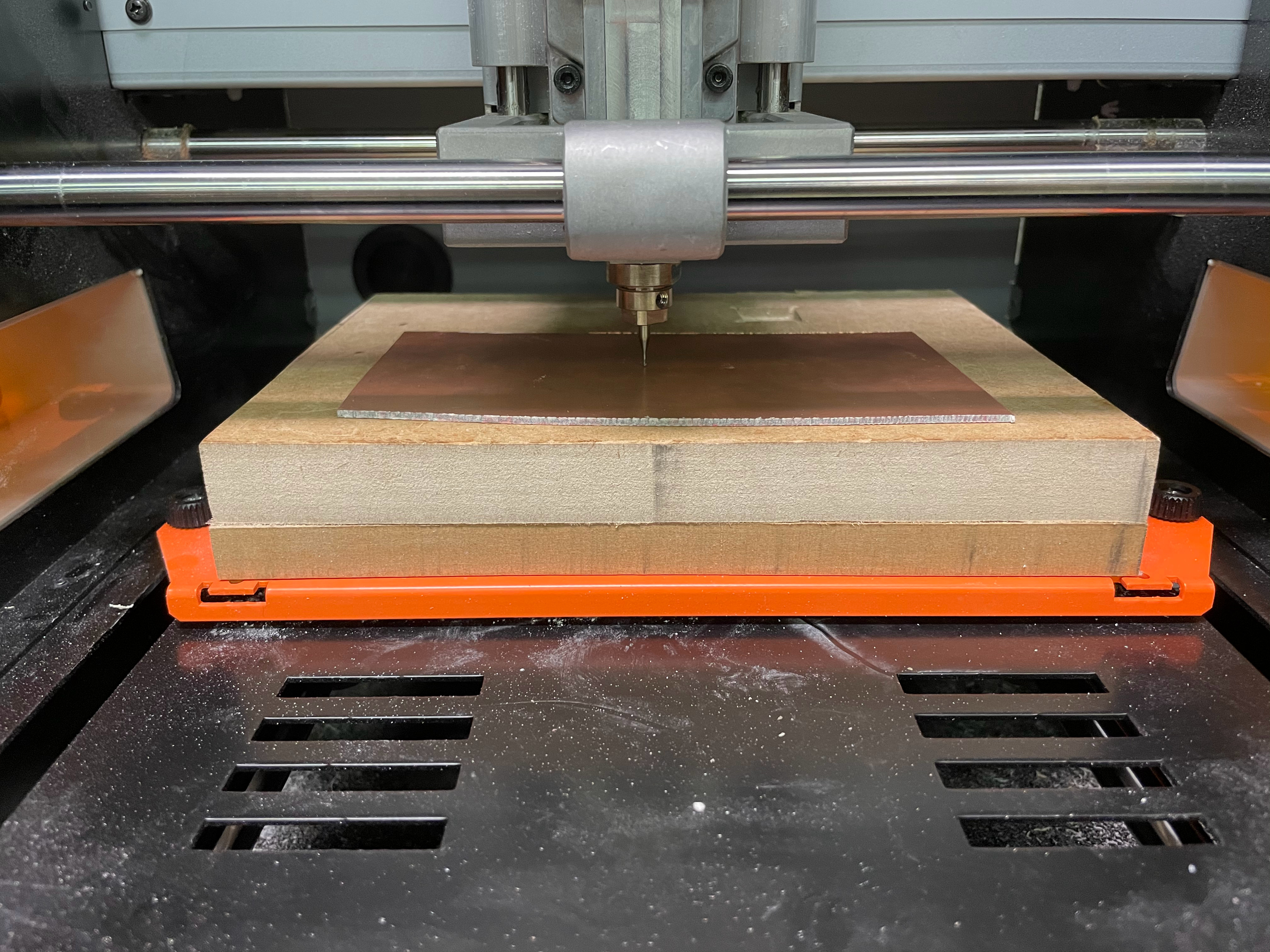
We started the lab on Thursday by learning more about the aforementioned remarkable Roland and found out some pretty neat things.
We began with a more general scope, learning first about feed rate. Through group research, we learned that feed rate is characterized by the distance that is travelled when the spindle rotates one revolution while spindle speed is how fast the spindle rotates. It is measured in revolutions per minute (RPM). Many of the terms sounded similar at first, so it was helpful to focus on discovering the differences between them and learning more about how to use them properly when manufacturing. Plunge rate is the initial speed that the bit is moved down into the material. The rate is specifically the initial speed since the hardness of the material, the bit, and many other factors can affect the bits movement along the z-axis during the cut. Depth of cut is how deep into a material the end mill cuts each pass. In other words, it’s how much material is removed per pass, and it’s typically measured in mm. If you set the z origin to be the top of the material, the depth of cut is the vertical distance between the origin and the end mill. Tooling was a term that at first seemed too vague to be an important topic, however I now realize that it is extremely important in the process of fabrication. Tooling is the process of designing and manufacturing components necessary to manufacture things down the line (i.e. a mold, jigs, fixtures, etc).
We also took some time to learn more about our specific Roland SRM-20, the notes of which I included below:
- Roland SRM20 can cut many materials such as PC board, acrylic, poly acetate, ABS, chemical wood, modeling wax, and foam.
- Bed size: 9.14 (X) x 6.17 (Y) inches
- Maximum material height: less than 5.15 in
- Maximum material weight: 4.4 lbs
- Mechanical Resolution: 0.0000393 inches/step
- Software: 0.000039 inches/step (RML-1), 0.000039 inches/step (NC code)
- Operating Speed: 0.24 – 70.87inch/min
- Spindle Rotation Speed: Adjustable 3,000 – 7,000 rpm

During our lab on Thursday, we started off by cutting out the design that Neil showed in class on the Roland Mill. The design (shown above) helps us better understand the precision of the mill with different sized bits. The upper half of the lines show the smallest possible gaps that the mill is able to etch out while the bottom half realtes to the smallest possible gaps that the mill is able to leave out while cutting around it.
We started by opening up Mods and opening up a server program for cutting on a Roland Mill (PCB png). After adding the PNG of the design (outline and trace), setting the right trace settings ("mill traces (1/64)" for etching and "mill outline (1/32)" for cutting out the outline from the material), and subbing out the "WebSocket Device" node for a "save file" node from the modules --> open server module --> file --> save menu. We then hit calculate on the "mill raster 2D" node in order to calculate the tool paths.
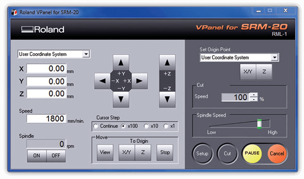
I had used the Roland Mill once before and it was nice to be able to take the time to get more comfortable with the machine. We used the software VPanel in order to control the mill from a PC. This software helped us send our design to the mill and set the correct X/Y and Z coordinates to home our mill to. In order to 0 the Z axis for the cut, we did not have an automated setting such as the larger Axiom mill, and had to instead put in the bit farther than normal, bring the bit down to just above the material, loosen the collet and have the bit drop down onto the material. We then 0 the Z within VPanel, and lift the Z-axis up above the material so it doesnt etch into the material as it starts turning on to begin the cut.
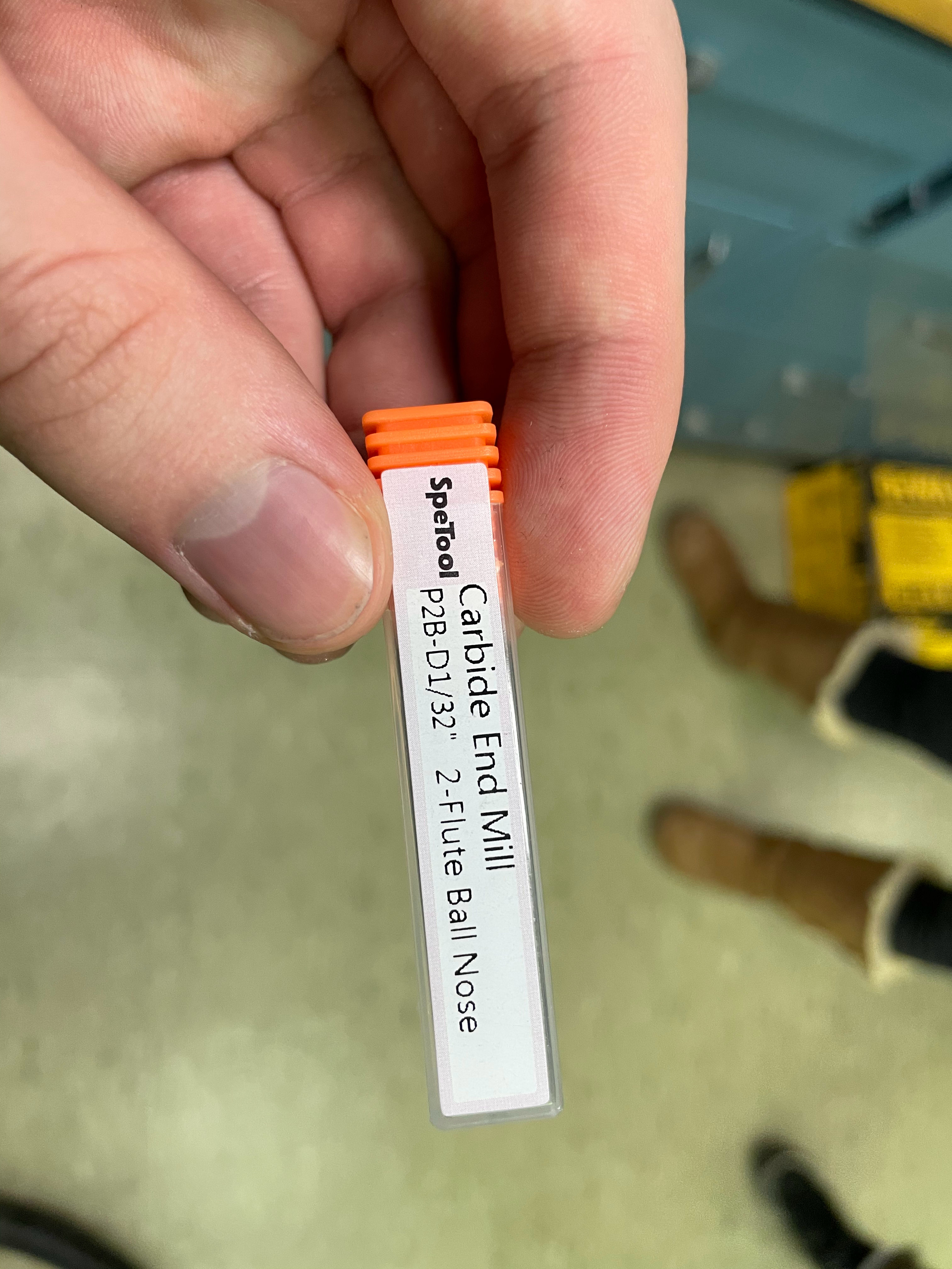
For etching out the design, we used a Cardide End Mill P2B-D1/32" 2-Flute Ball Nose bit.
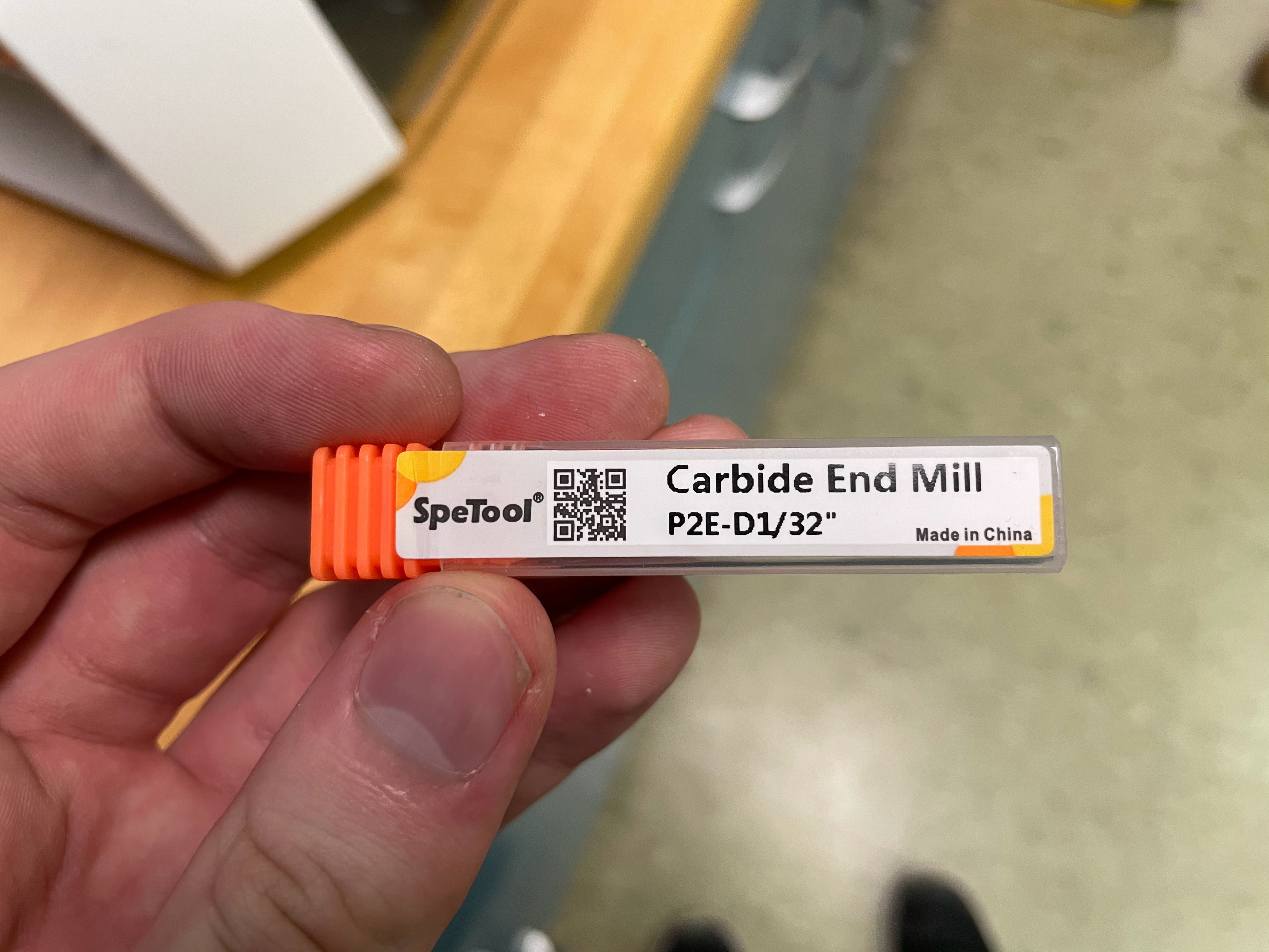
For cutting out the design from the rest of the material, we used a Cardide End Mill P2E-D1/32" bit.
The end product came out as shown, and I was impressed by the performance of the 1/32" bit. As you can see, the roland was able to easily cut around the .010 jut-out, and was able to do a clean job of the gap around the .017 point. This was similar to Neil's example with a 1/64" bit, and the results being slightly less precise in our experiment make sense since we are using a bit with twice the diameter.
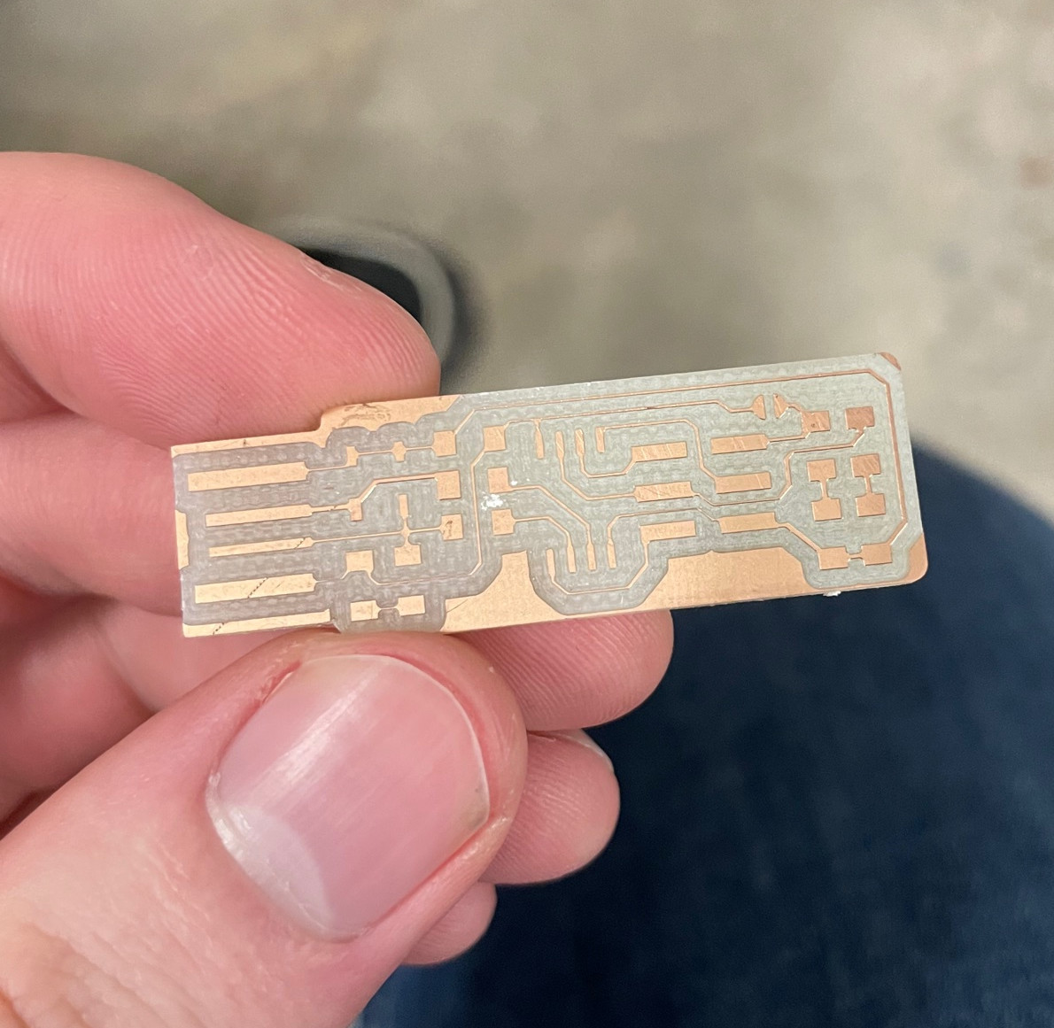
We also milled out a TinyISP using our Roland and Neil's files (linked at the bottom of the page). To do this, we used mods, and then cut out the design onto a material that had a base of fiberglass and a top coating of copper. The copper top would be conductive and the fiberglass would work as an insulator for our circuit board.
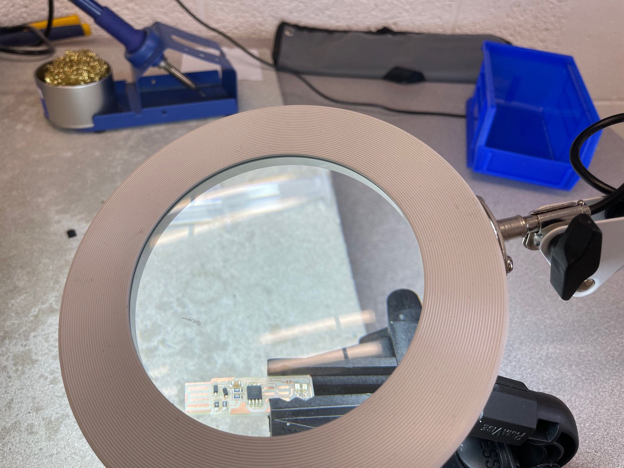
We then began the process of soldering on the components of our circuit with a syringe of flux and a hot air gun, which was a new and incredibly enjoyable experience for me. Although I began strong by adding a resistor in the wrong location, I eventually began to get the hang of it.
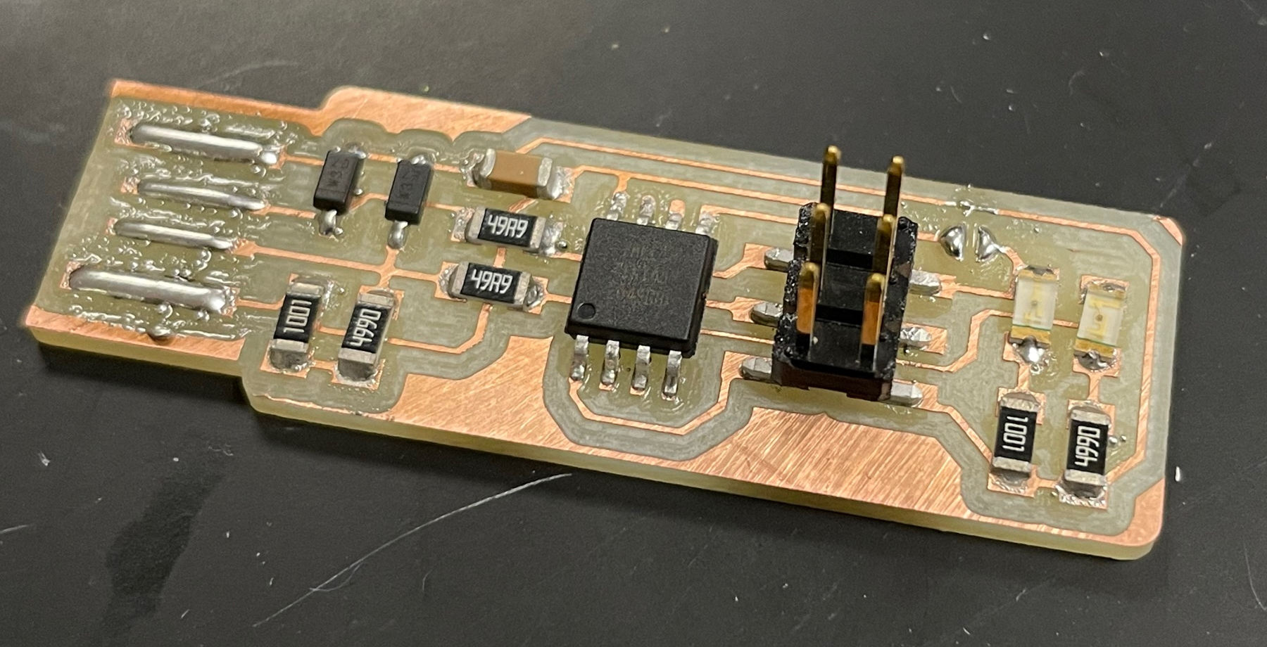
After finally adding all of the components, completing the jumper, shaving off the extra copper on the USB end, and adding solder to the USB connection, it was finally time to program the TinyISP. To do this, I (with the gracious help of Professor Goodman) used gedit and the linux command line to program the device. As we plugged it in, it showed up as a USB device (WHICH MEANS THAT THINGS DID NOT GO HORRIBLY WRONG :D )!!! In order to finish up this process, we used another classmates TinyISP and, after all was said and done, I disconnected the jumper and exhaled loudly. My circuit board took many tries, often failing from not enough solder on the 2 middle prongs of the USB connection or a diode facing the wrong direction. I am extremely pleased with my final product and am looking forward to partaking in more soldering and electronics down the line.