Jacob Libby
Week 10
Input Devices
A week dedicated to learning more about circuits and input devices
We began this week with the group project of exploring input devices with a small lecture and lab focused on PIR sensors, photoresistors, joysticks, and other such components.
Of these input devices, the most intriguing to me was the photoresistor, as it seemed to work by magic. I have become very used to electronic components to work via manual tilting, twisting, pushing, etc, however the simple act of increasing or decreasing the amount of exposed light to affect the resistance was so cool to watch!
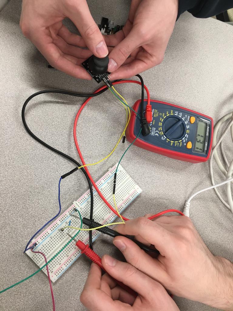
We spent a good while moving our hands over the photoresistor and away from it and watching the multimeter go up and down.
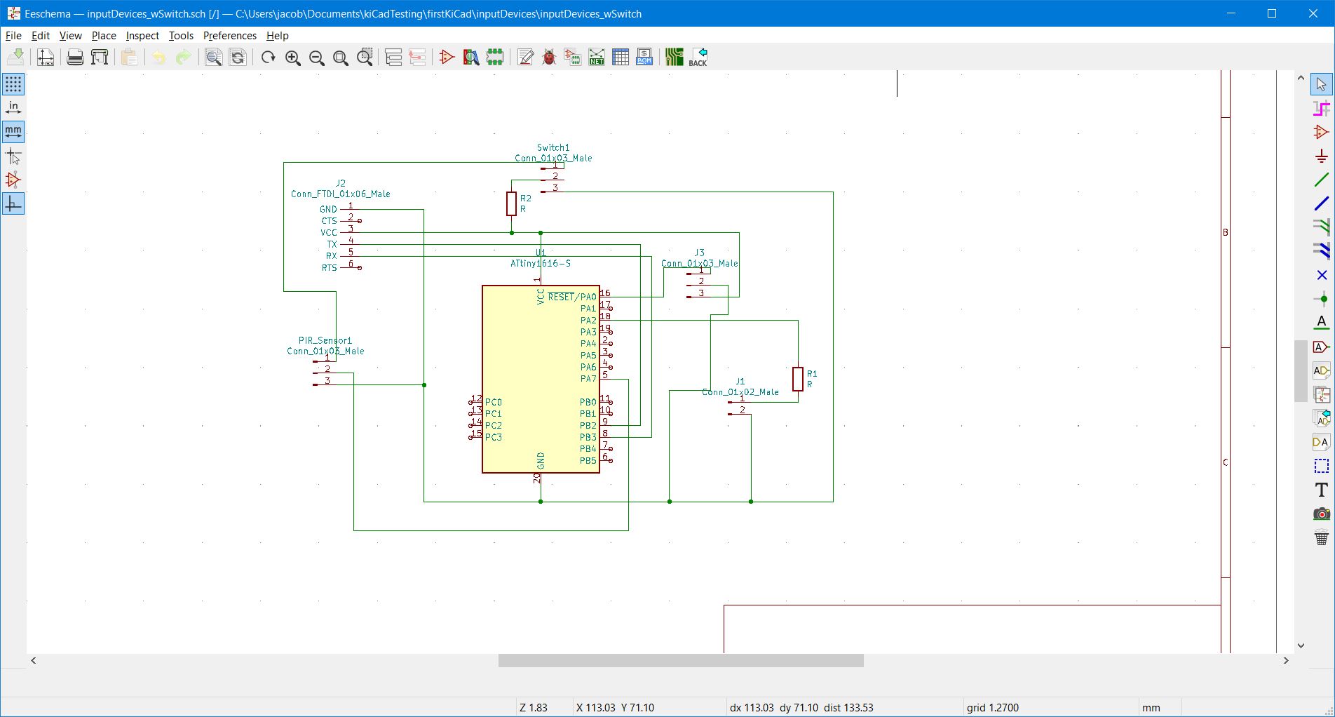
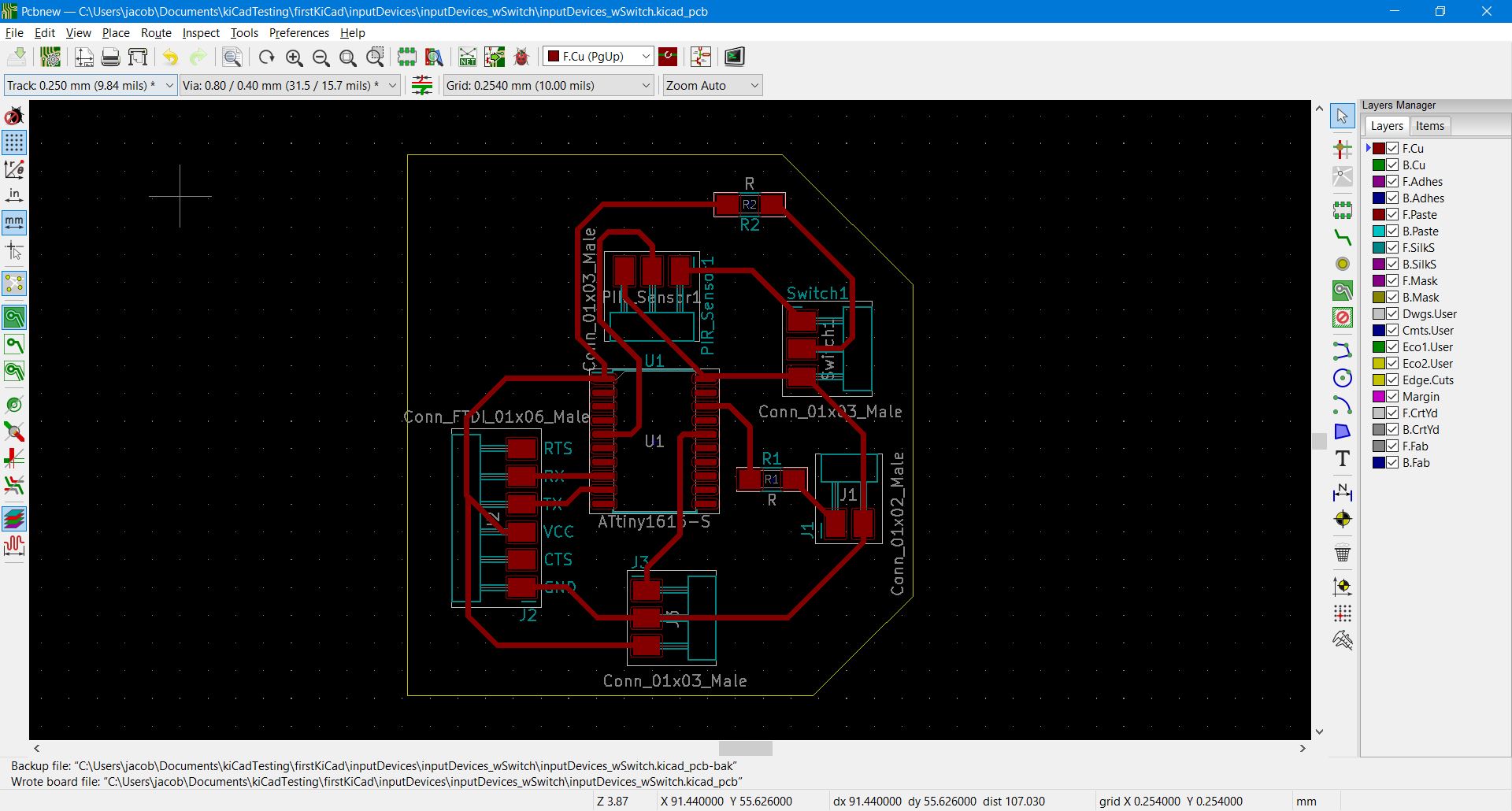
For the individual project, we had to design, mill, solder, and program a new board that utilized input devices, which seemed like a large task given how time consuming and error-inducing the past similar weeks had been. I started the week by launching kiCad and sifting through the available input devices that we were able to use in our designs. I ended up landing on the idea of using a switch to allow power to a PIR sensor that senses movement and when it does (and the switch is on), a sound would play on a piezo buzzer. This would be a very crude design for a motion detector or security system, and my hopes were far higher with this design than I was expecting.
The process of connecting traces was far easier with these parts than my previous board, and it needed minimal traces that went under components.
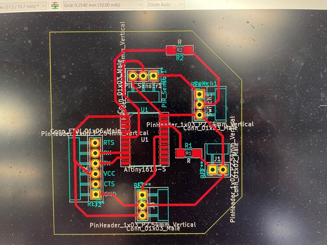
The first large hurdle to overcome was the transition from illustrator to Mods. After finishing the design in kiCad, I exported the SVG into Illustrator and then ensured that traces would work properly. After doing this, I made sure that the design had a background for the through-holes, outline, and traces, and tried sending it into mods. This task was surprisingly difficult, and it took me hours to figure out it was a problem with how Mods was interpreting the file size, as it read that it was NaN and did not show in the visual preview pane. I sought out help and ended up needing to use a PNG and going through a few more hurdles such as resetting the background to White, setting the DPI to 300, and inverting the image. This eventually worked and thus began the third hurdle of milling.
As the design began cutting (on our Roland SRM-20) I realised that there was a problem with the trace. As it started cutting, the ball end bit was just grazing the top of the copper, and not cutting deeply enough into it.
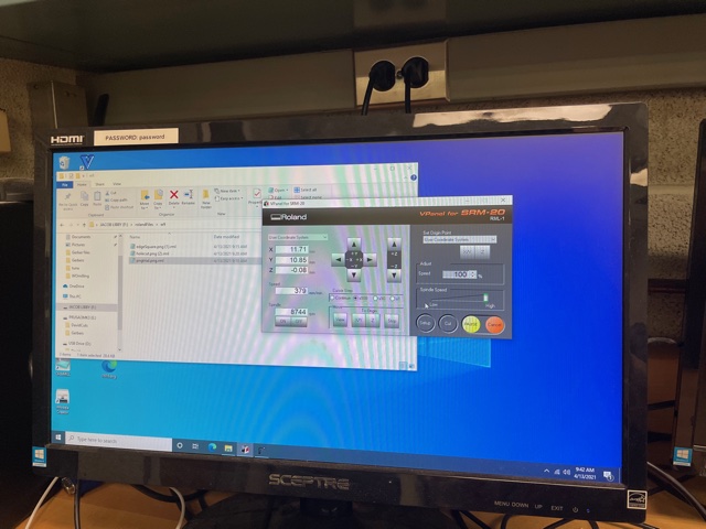
After a half hour of trying to re-zero and re-zero the machine, it still was occuring, and I ended up having to slightly lower the z by .08 mm twice before it actually cut out the traces.
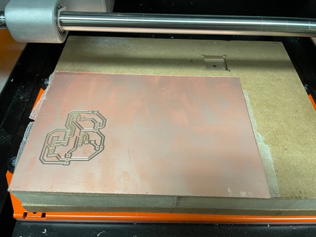
The cuts went well for the outline, but once the mill started cutting out the through-holes I had a bad feeling (incoming hurdle number 2). I noticed as the drill lowered, it seemed to be cutting a very large through-hole, and I crossed my fingers that my eyes were just deceiving me and it was actually cutting out the perfect size hole.
... it wasn't ...
The bit cut out an incredibly large hole for each through-hole and trying to put a pin header in the holes was very loose and I knew that this wouldn't work. As I was trying to fix this, someone in my class was (VERY LUCKILY) in the lab and asked if I had thought of using SMD pins instead, which I had not thought of and praised the idea and his intellect (thank you, Kevin).
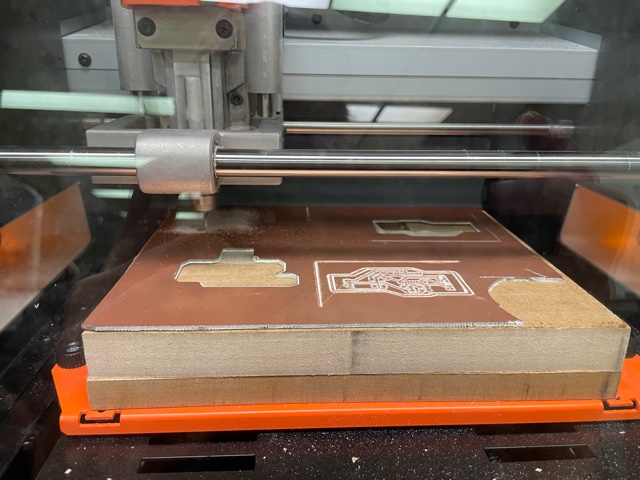
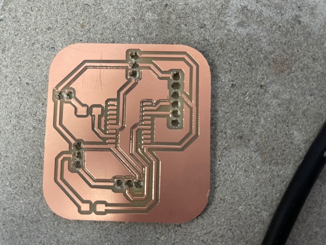
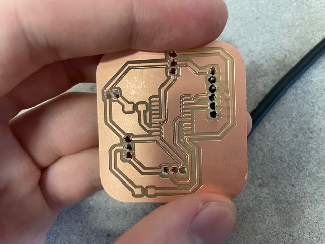
I redid the design in kiCad and was much more optimistic with the exclusion of through-holes. I cut out the design and was much happier with this version.
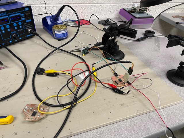
After cutting it out, I began the process of soldering the board and adding all of the pins for the components, which took a surprisingly long amount of time and I finally got all of the components connected. Although he wasn't necessarily a "looker", he had a decent personality and thats really what matters.
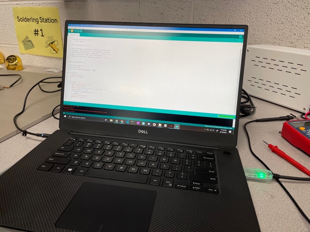
Welcome, my friends to Arduino. As I began coding the ATTiny1616, I had a bad taste in my mouth from prior weeks where the coding did not work due to errors that were unsolvable for me and my classmates. Everything started going well until first, the Hello World did not work, which made me very sad. As I was trying to get the Hello World to work, I encountered a very sad and infuriating error that I was unable to get past. Arduino noted that UPDI Initialisation Failed, however that was not very helpful, and after switching out all connections and scouring the worldwide web, nothing seemed to work. I encountered a previous Fab Academy Student's Page where they encountered the same problem and found a way past it. I tried following the instructions, but for some reason the code was unable to be uploaded to the arduino, and after hours of trouble shooting again, I worked on polishing my code and have uploaded all files below.
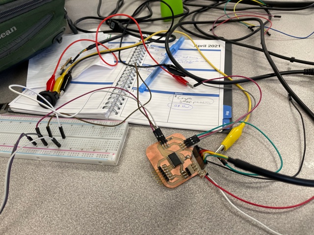
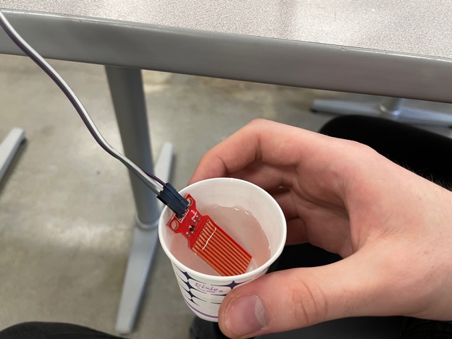
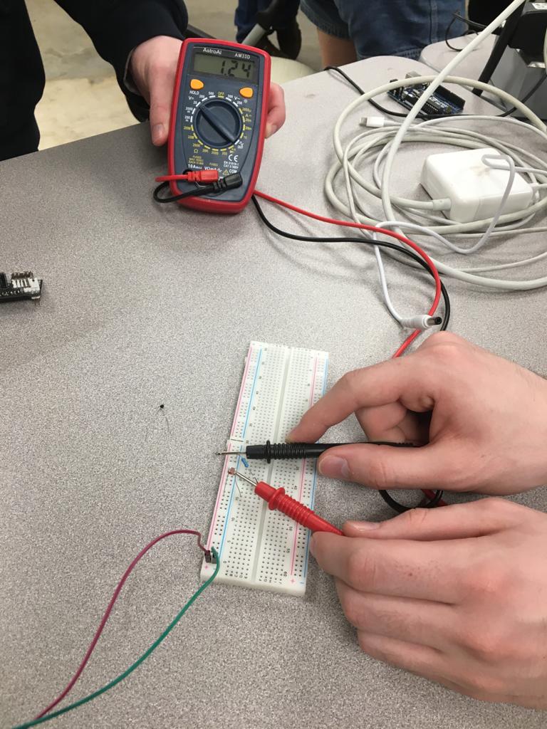
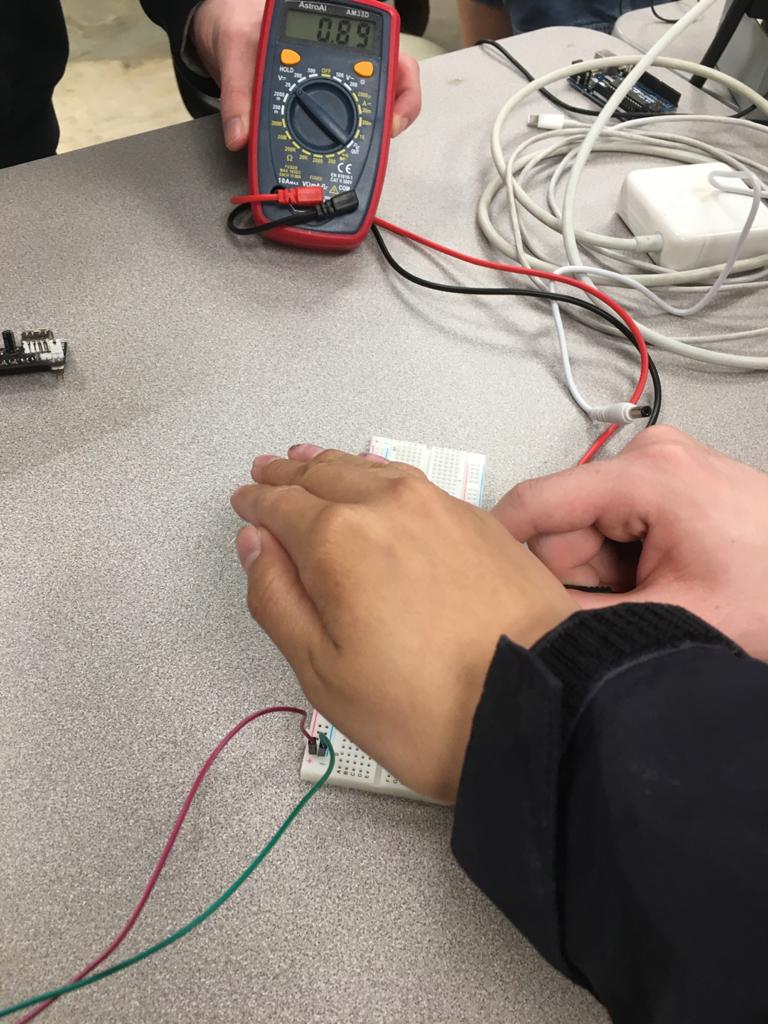
After taking a short mental health break from input devices, I actually was able to come back and crank out some more work. I ended up spending even more hours to try and figure out the UPDI error, and I (as well as my TA and instructors) was unable to figure out how to fix it. At a loss, I resoldered a new ATTiny1616, which somehow worked! I then moved on to perfecting the code and plugging in the PIR sensor, the buzzer, and the rocker switch. The switch and piezo buzzer were easy enough to hook up (only needing minor altercations to actually work with headers), however I had a very difficult time getting the PIR sensor to work. After hours of trying to get the sensor to work and testing everything with a multimeter over and over again, I switched gears and found a water level sensor. I plugged it into the port that I had made for the PIR sensor (it was a blessing that it had the appropriate pins and numbers of pins), altered my code, and uploaded it to the board. AND IT WORKED!
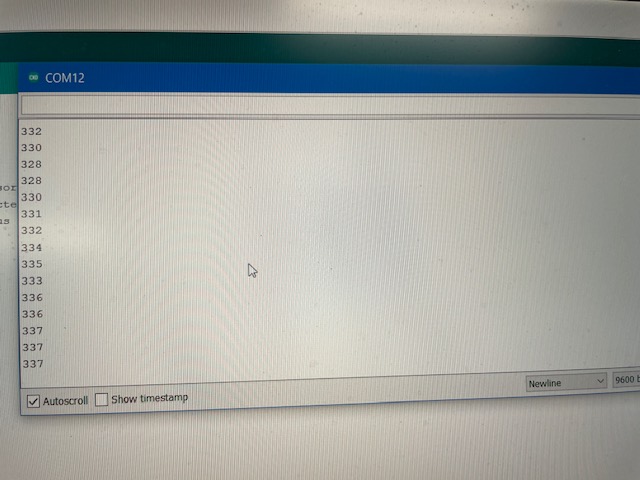
To make sure that the sensor and board were actually reading new values at each iteration of the loop, I made the code write the values into the Serial Monitor, and it looked great!!!!! The values that it is spitting out correlates to the amount of humidity that the sensor is detecting (higher numbers meaning more humid and vice versa). As I dipped the sensor into the water, the values started to climb, and when I took out the sensor and dried it off, the values decreased. YAY! Input devices: down, Output devices, here I come....
.rml)